
Cooling mechanism for threaded shaft of water feeding pipe die

A technology of water supply pipe fittings and cooling mechanism, applied in the field of plastic pipe fitting moulds, can solve the problems of low production efficiency, inability to cool down the heat in time, affecting the shaping cycle of pipe fittings, etc.

Active Publication Date: 2013-09-18
YONGGAO CO LTD
View PDF4 Cites 2 Cited by
  • Summary
  • Abstract
  • Description
  • Claims
  • Application Information

AI Technical Summary

Problems solved by technology

In the prior art, since the threaded shaft needs to be rotated when demoulding, the rotating threaded shaft cannot be directly connected to the inlet and outlet of the cooling water pipe (the leather pipe of the cooling water circuit will be entangled when rotating), so designing the cooling water channel in the rotating threaded shaft becomes a problem. It is a difficult task, but the heat generated in the production of pipe fittings cannot be cooled in time, which will easily affect the shaping cycle of the pipe fittings, cause the pipe fittings to shrink and deform, the scrap rate is high, and the production efficiency is low

Method used


Image

  • Cooling mechanism for threaded shaft of water feeding pipe die
  • Cooling mechanism for threaded shaft of water feeding pipe die

Examples


Embodiment Construction

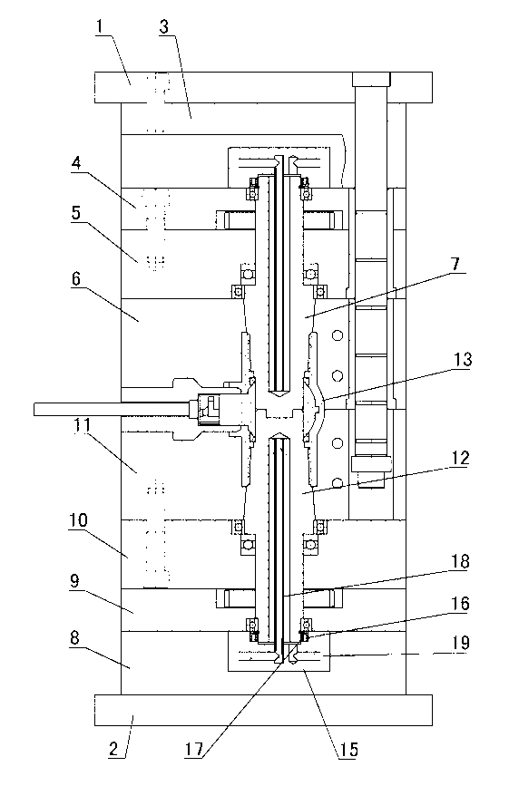
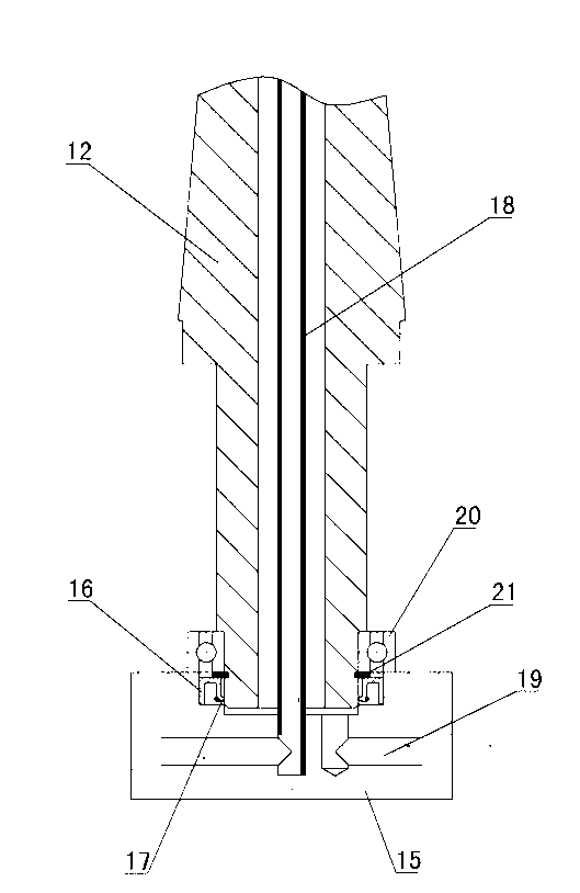
[0009] The invention relates to a cooling mechanism for a threaded shaft of a water supply pipe mold, such as figure 1 , figure 2 As shown, it includes the fixed mold seat plate 1 and the movable mold seat plate 2 of the mold, the fixed mold fixed plate 3, the fixed mold gear plate 4, the fixed mold bearing plate 5 and the cavity plate 6 are installed under the fixed mold seat plate 1, and the cavity plate 6 is provided with a cavity threaded shaft 7, a mold foot 8 is installed on the movable mold seat plate 2, a movable mold gear plate 9, a movable mold bearing plate 10 and a core plate 11 are installed on the mold foot, and the core plate 11 is provided with The core threaded shaft 12, the head of the core threaded shaft 12 corresponds to the head of the cavity threaded shaft 7, and the cavity is formed between the core threaded shaft 12 and the cavity threaded shaft 7, the cavity plate 6 and the core plate 11 , there is a formed pipe fitting 13 in the cavity, which is cha...


PUM


Abstract

The invention discloses a cooling mechanism for a threaded shaft of a water feeding pipe die. The cooling mechanism comprises a fixed die seat plate and a movable die seat plate, wherein a fixed die fixing plate, a fixed die gear plate, a fixed die bearing plate and a cavity plate are arranged below the fixed die seat plate; a cavity threaded shaft is arranged in the cavity plate; a die foot is arranged on the movable die seat plate; a movable die gear plate, a movable die bearing plate and a core plate are arranged on the die foot; a core threaded shaft is arranged in the core plate; the head of the core threaded shaft corresponds to that of the cavity threaded shaft; the core threaded shaft and the cavity threaded shaft respectively form a cavity together with the cavity plate and the core plate; a formed pipe is arranged in the cavity. The cooling mechanism is characterized in that water sealing glands are arranged at the end parts of the cavity threaded shaft and the core threaded shaft; framework sealing rings are arranged in the water sealing glands; lips of the framework sealing rings are in contact with the outer walls of the end parts of the cavity threaded shaft and the core threaded shaft; cooling water pipes are respectively arranged in the cavity threaded shaft and the core threaded shaft; cooling water holes are formed in the water sealing glands; the cooling water pipes are communicated with the cooling water holes.

Description

technical field [0001] The invention relates to a cooling mechanism for a threaded shaft of a water supply pipe fitting mould, which belongs to the field of plastic pipe fitting moulds. Background technique [0002] At present, in the production of threaded water supply pipe fitting molds, the thread demoulding of pipe fittings generally uses an automatically rotating threaded shaft (core), which is driven by an electric motor or an oil motor through a gear. In the prior art, since the threaded shaft needs to be rotated when demoulding, the rotating threaded shaft cannot be directly connected to the inlet and outlet of the cooling water pipe (the leather pipe of the cooling water circuit will be entangled when rotating), so designing the cooling water channel in the rotating threaded shaft becomes a problem. It is a difficult task, but the heat generated in the production of pipe fittings cannot be cooled in time, which will easily affect the shaping cycle of the pipe fittin...

Claims


Application Information

Patent Timeline
IPC IPC(8): B29C33/04B29C33/44
Inventor 卢震宇周正杰王紫萱陈卫
Owner YONGGAO CO LTD
Learn More