


Quick Research
Generate reliable direction feasibility study reports for your R&D in just a few steps.

Technical Q&A
Discover and master advanced knowledge NOW. Basics, ideas, possibilities, all at once.

Find Solutions
As an expert in R&D theories, this can generate solutions to your technical problems instantly.

Evaluate Feasibility
Analyze your overall solution with one click, know your potential R&D risks in advance.

Monitor Landscape
Get weekly tech updates, stay abreast of the latest tech innovations and key insights.
Circuit arrangements for electronically controlled DC networks
A series circuit and current direction technology, applied in the field of switching devices, can solve problems such as increased overhead and on-state loss, and achieve the effects of reduced circuit overhead, reliable function, and free cascading.
- Summary
- Abstract
- Description
- Claims
- Application Information
AI Technical Summary
Problems solved by technology
Method used
Image

Examples
Embodiment Construction
[0056] Figures 1 to 3 have already been described as belonging to the prior art in the background section of the description.
[0057] Figure 4 A unipolar DC switch is shown, which is used for disconnecting the positive line (P1 relative to P11 ) in a simple, usually grounded DC network on one side (direct voltage or direct current network). This device may be sufficient if the negative wire (N0) is explicitly grounded.
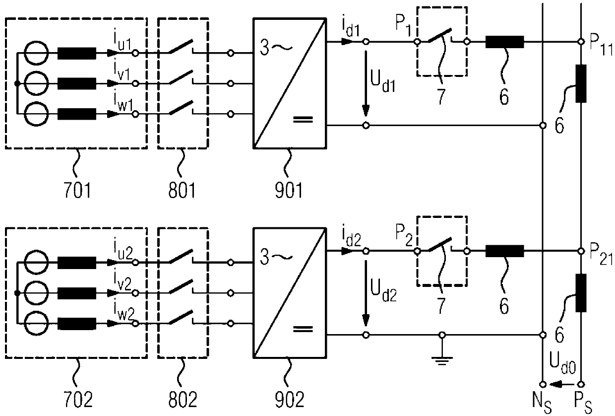
[0058] Figure 5 shown with Figure 4 A similar arrangement, however, has a plurality (here, for example: two) DC switches, which lead to a common busbar (PS).
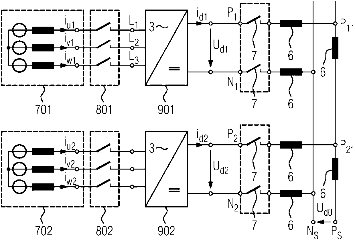
[0059] Figure 6 shown with Figure 4 Similar arrangement, however with the addition of another DC link with negative polarity and associated switches. In this case, the DC voltage of the positive conductor (UP1 relative to N0) and the DC voltage of the negative conductor (UN2 relative to N0) are usually chosen to be equal in value, the DC voltages being measured in each case relative to a com...
PUM
 Abstract
Description
Claims
Application Information
 - R&D Engineer
- R&D Manager
- IP Professional
- Industry Leading Data Capabilities
- Powerful AI technology
- Patent DNA Extraction
Browse by: Latest US Patents, China's latest patents, Technical Efficacy Thesaurus, Application Domain, Technology Topic, Popular Technical Reports.
© 2024 PatSnap. All rights reserved.Legal|Privacy policy|Modern Slavery Act Transparency Statement|Sitemap|About US| Contact US: help@patsnap.com