
Multi-wavelength passive optical network system

A passive optical network, multi-wavelength technology, applied in the field of optical access, can solve the problem of time division characteristics affecting the bandwidth of optical network units, and achieve the effect of meeting the growing demand and improving the overall bandwidth

Inactive Publication Date: 2013-09-11
秦臻
View PDF10 Cites 2 Cited by
  • Summary
  • Abstract
  • Description
  • Claims
  • Application Information

AI Technical Summary

Problems solved by technology

[0004] In the above-mentioned traditional point-to-multipoint passive optical network system, since the optical network units share the optical transmission medium in the way of time division multiplexing, under the network architecture with a large branch ratio, the time division characteristics of the time division multiplexing mode seriously affect the optical Network element bandwidth
Therefore, with the development of broadband services, traditional passive optical network systems cannot meet users' increasing demand for bandwidth

Method used


Image

  • Multi-wavelength passive optical network system

Examples


Embodiment Construction

[0017] The technical solutions in the embodiments of the present invention will be clearly and completely described below. Obviously, the described embodiments are only a part of the embodiments of the present invention, rather than all the embodiments. Based on the embodiments of the present invention, all other embodiments obtained by those of ordinary skill in the art without creative efforts shall fall within the protection scope of the present invention.

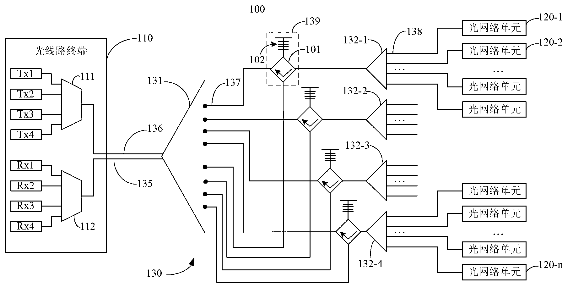
[0018] see figure 1 , which is a schematic diagram of a preferred embodiment of the multi-wavelength passive optical network system provided by the present invention. The passive optical network system 100 includes at least one optical line terminal (OLT) 110 , a plurality of optical network units (ONUs) 120 - 1 to 120 - n and an optical distribution network (ODN) 130 . The optical line terminal 110 is connected to the plurality of optical network units 120 - 1 to 120 - n in a point-to-multipoint manner through the opt...


PUM


Abstract

The invention provides a multi-wavelength passive optical network system which comprises an optical line terminal, an optical distribution network and a plurality of optical network units. The plurality of optical network units are divided into multiple groups, and different uplink and downlink wavelengths are adopted for each group of optical network units. The optical distribution network comprises a first stage optical splitter and a plurality of second stage optical splitters. The first stage optical splitter comprises an uplink public port, a downlink public port, a plurality of uplink branch ports and a plurality of downlink branch ports. The uplink public port and the downlink public port are connected onto the optical line terminal through an uplink main optical fiber and a downlink main optical fiber respectively. The downlink branch ports and the uplink branch ports of the first stage optical splitter are connected onto downlink branch optical fibers and uplink branch optical fibers respectively and are connected onto one group of optical network units through one second stage optical splitter. Each wave dividing assembly comprises optical circulators with four ports and fiber bragg gratings, and the fiber bragg gratings of different wave dividing assemblies have different reflectance spectrums.

Description

technical field [0001] The present invention relates to an optical access technology, in particular, to a multi-wavelength passive optical network (Passive Optical Network, PON) system. Background technique [0002] As users' demand for bandwidth continues to grow, traditional copper wire broadband access systems are increasingly facing bandwidth bottlenecks. At the same time, the optical fiber communication technology with huge bandwidth capacity is becoming more and more mature and the application cost is decreasing year by year. Optical access technology, such as passive optical network, has gradually become a strong competitor of the next generation broadband access network. [0003] Traditional passive optical network systems, such as Gigabit-capable Passive Optical Network (GPON) systems or Ethernet Passive Optical Network (EPON) systems, generally use point-to-multipoint ( Point to multiple point, P2MP) network architecture, that is, the optical line terminal (Optica...

Claims


Application Information

Patent Timeline
Patent Type & Authority Applications(China)
IPC IPC(8): H04Q11/00
Inventor 杨珍珍
Owner 秦臻
Learn More