
Direct type backlight luminance compensation method and display device

A backlight brightness and brightness compensation technology, applied in the display field, can solve the problems of increasing storage hardware volume, image distortion, and increasing storage capacity

Active Publication Date: 2013-09-11
HISENSE VISUAL TECH CO LTD
View PDF6 Cites 58 Cited by
  • Summary
  • Abstract
  • Description
  • Claims
  • Application Information

AI Technical Summary

Problems solved by technology

[0003] However, in the existing backlight brightness compensation, one is: only consider the backlight brightness of the area where the pixel is located, ignore the influence of other areas outside the area where the pixel is located on the brightness of the area where the pixel is located, and directly compensate the brightness, resulting in a larger image compensation. The other is: while considering the brightness of the backlight in the area where the pixel is located, the influence of the brightness of other areas is considered, and then the compensation of the image to the brightness is considered comprehensively. However, when considering the influence of adjacent areas on the brightness of this area, it is through The statically set table in advance stores the compensation coefficients that take into account the influence of brightness between different adjacent areas, and realizes brightness compensation through table lookup and calculation, so that the different effects of different brightness in each area are not considered comprehensively. Although this method is better than the first One method optimizes the display image, but the optimization effect needs to be further strengthened
In addition, while the optimization of the table image display effect using the static settings is limited, the storage capacity is further increased, and the volume of the storage hardware is increased. The increase in the volume of the storage hardware directly leads to the integration of the storage hardware. The increasing number of limiting factors in the design, packaging and printing of chips and circuits is also contrary to the development trend of integration, miniaturization and thinning of existing display devices.

Method used


Image

  • Direct type backlight luminance compensation method and display device
  • Direct type backlight luminance compensation method and display device
  • Direct type backlight luminance compensation method and display device

Examples


Embodiment 1

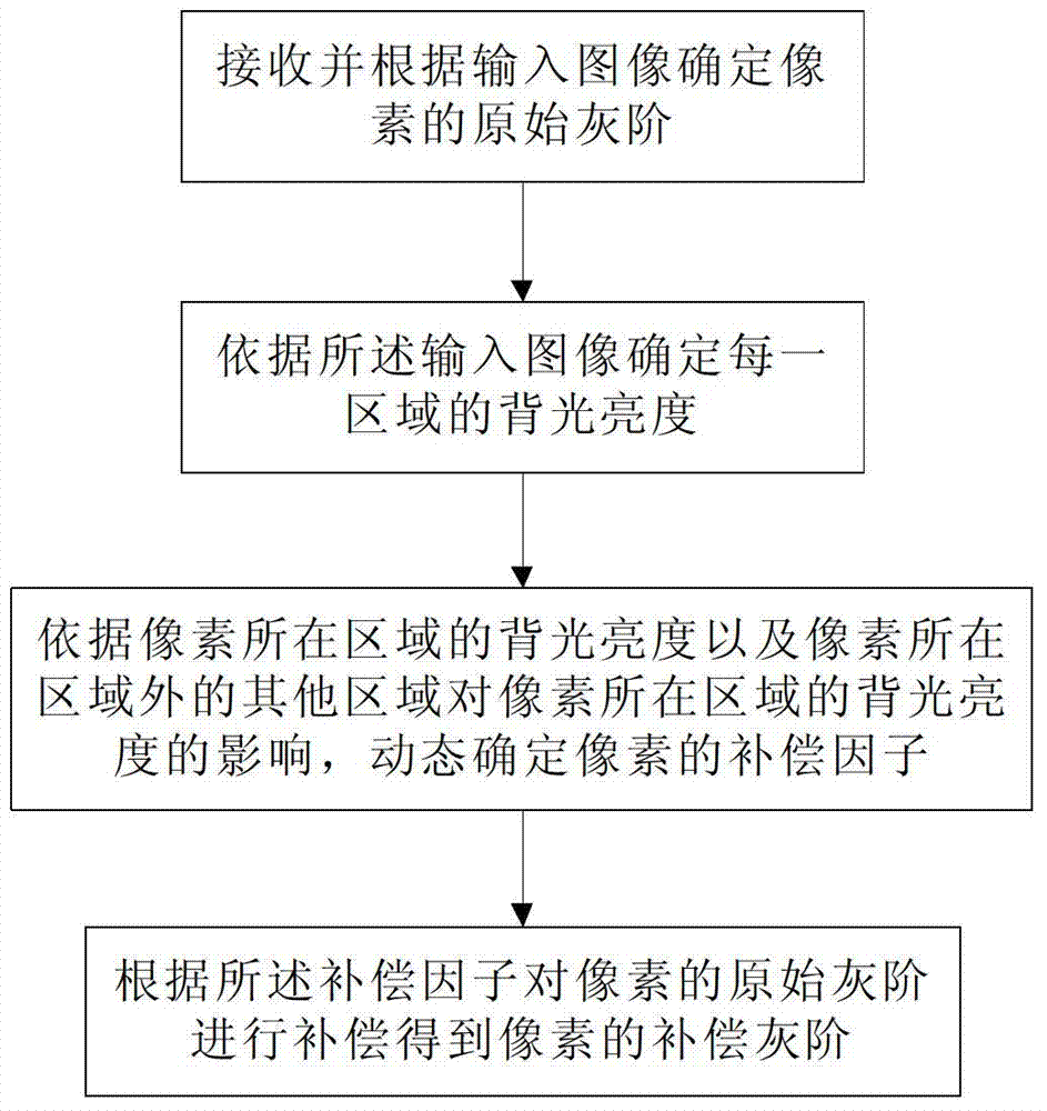
[0080] like figure 1 As shown, the brightness compensation method of the direct type backlight in this embodiment adopts the above-mentioned principle to compensate the brightness, specifically including:

[0081] Receive and determine the original grayscale of the pixel (i, j) according to the input image;

[0082] i is the row number of the pixel; j is the column number of the pixel; specifically, for a display panel of 1024*768, the corresponding i value ranges from 1 to 1024, and the corresponding j value ranges from 1 to 768; and the said The calculation of the row number and the column number of the pixel is relative. The column number can be calculated from the left side of the display panel or from the right side of the display panel. The row number can be calculated from the top of the display panel or from the bottom of the display panel. end start;

[0083] Determine the backlight brightness of each area according to the input image; the area is pre-allocated, and...

Embodiment 2

[0088] In the specific implementation process, there are many methods for determining the brightness of the backlight, such as using the histogram statistical method, etc., but on the basis of the previous embodiment, this embodiment provides a method with a small amount of calculation and simple way,

[0089] In this embodiment, the calculation of the brightness value of the backlight includes the following steps:

[0090] Determine the initial backlight brightness control value before filtering according to the current frame input image;

[0091] Input the initial backlight brightness control value before filtering into the filter, and process the filter to obtain the final backlight brightness control value after filtering, which is specifically determined by the following formula;

[0092] BL m '(n)=Local avg +k×(Local max -Local avg );

[0093] BL m (n)=(1-c)BL m (n-1)+cBL m '(n);

[0094] in,

[0095] The BL m '(n) is the initial backlight brightness control ...

Embodiment 3

[0107] On the basis of Embodiment 2, this embodiment proposes a specific method for calculating the compensation factor, which is as follows:

[0108] The specified area is an area other than the area where the pixel (i, j) is located

[0109] The compensation factor f com (i, j) is solved by the following formula:

[0110] f com ( i , j ) = ( Σ m = 1 M w m ( i , j ) Σ m ...


PUM


Abstract

The invention discloses a direct type backlight luminance compensation method and a display device, and is designed for solving the problems that image distortion is large after luminance compensation in the existing direct type backlight luminance compensation methods. The direct type backlight luminance compensation method includes: receiving and confirming original gray scale of pixel (i,j) according to input images; confirming backlight brightness of each area according to the input images; dynamically confirming compensating factors fcom (i,j) according to backlight brightness in pixel (i,j) area and influence on backlight brightness from other areas outside the pixel (i,j) area to the pixel (i,j) area; compensating original gray scale of pixel (i,j) according to the compensating factors fcom (i,j) to acquire compensating gray scale of pixel (i,j), wherein, i is taken as line number of pixel, and j is taken as column number of pixel. The direct type backlight luminance compensation method and the display device have the advantages that image distortion is small, data volume is small and the like after luminance compensation.

Description

technical field [0001] The invention relates to the display field, in particular to a brightness compensation method and a display device of a direct-lit backlight. Background technique [0002] The direct backlight is a backlight whose light source is located directly behind the display screen. In order to further improve the contrast of the display screen (such as a liquid crystal display screen), the backlight is divided into several areas in the form of a grid. During the specific operation process, according to the displayed image Individually control the backlight brightness of each area according to the demand, and then realize the backlight brightness compensation for each pixel displayed by controlling the parameters of the pixel itself such as light transmittance through the backlight brightness of different areas, so as to improve the contrast of the image and realize the optimization of the displayed image . [0003] However, in the existing backlight brightness...

Claims


Application Information

Patent Timeline
IPC IPC(8): G09G3/36H05B37/02
Inventor 刘丽丽刘卫东邢文峰孙志强
Owner HISENSE VISUAL TECH CO LTD
Learn More