
Simulation method for fluid mixing state

A fluid model and mixing technology, applied in CAD numerical modeling, special data processing applications, instruments, etc., can solve the problems of low filling rate, not representing the ideal mixing state, etc., to achieve the effect of improving development efficiency

Inactive Publication Date: 2017-10-24
SUMITOMO RUBBER IND LTD
View PDF3 Cites 0 Cited by
  • Summary
  • Abstract
  • Description
  • Claims
  • Application Information

AI Technical Summary

Problems solved by technology

[0010] However, in the actual mixing process, the filling rate is lower than 100%
Therefore, the ideal kneading state defined in Non-Patent Document 2 does not represent the correct ideal kneading state

Method used


Image

  • Simulation method for fluid mixing state
  • Simulation method for fluid mixing state
  • Simulation method for fluid mixing state

Examples


Embodiment Construction

[0045] Embodiments of the present invention will now be described in detail with reference to the accompanying drawings.

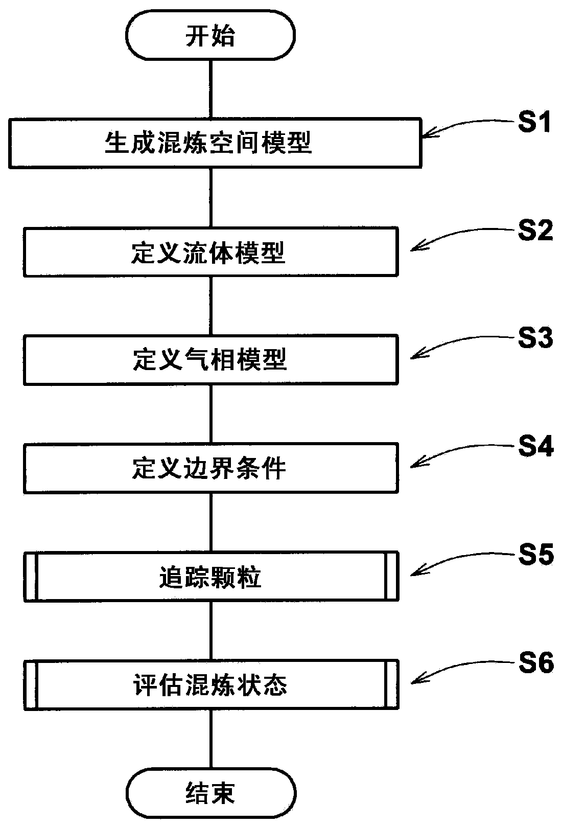
[0046] The present invention is directed to an analysis method for evaluating the kneading state of a fluid by using a computer (not shown).

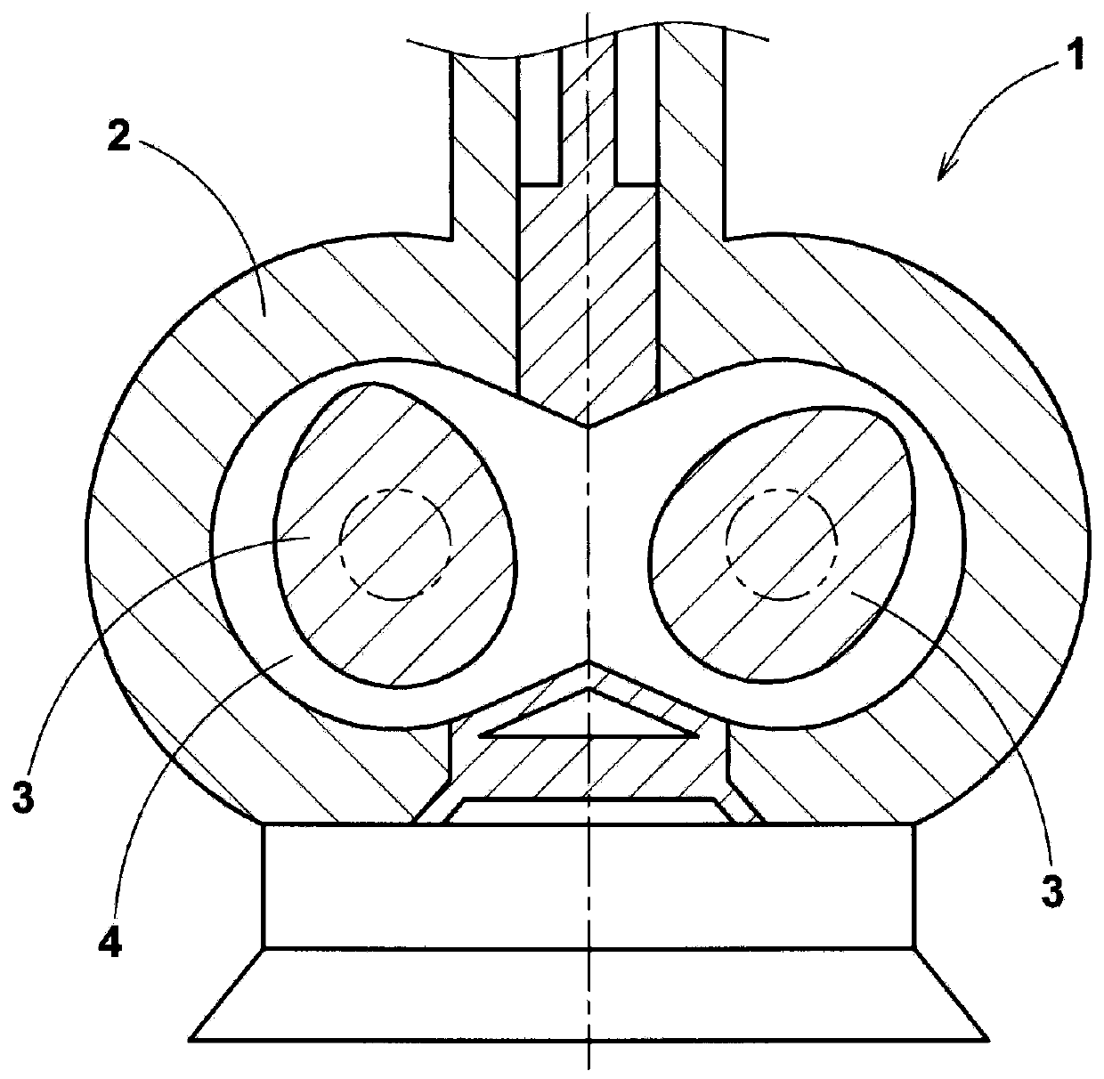
[0047] For example, before molding a rubber material or a numerical material, kneading is performed. During kneading, raw materials such as chemicals, fine particles, etc. are wetted with a liquid binder and dispersed uniformly into a homogeneous mixture. This mixing process is typically performed by figure 1 The Banbury kneader 1 shown is performed.

[0048] Banbury Mixer 1 includes:

[0049] The housing 2 defines the inner surface of a kneading space 4 in which raw materials such as rubber material etc. are kneaded, and a pair of rotors 3 which are rotatable in the kneading space 4 .

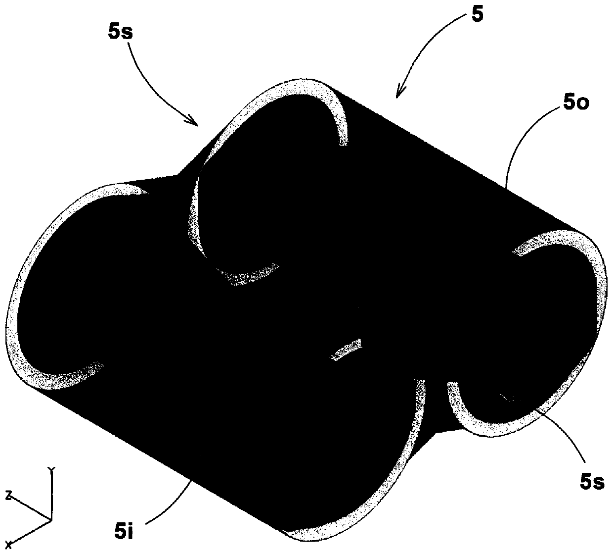
[0050] The kneading space 4 in this example has a figure 8-like sectional shape. However, the kneading space is not limited t...


PUM


Abstract

A computer analysis method for evaluating the kneading state of a fluid, comprising: a step of generating a finite element model of a kneading space in which the fluid is kneaded; a step of defining a model of the fluid; defining a filling rate in the kneading space model A step of fluid model below 100%, and defining required kneading conditions; a particle tracking step, in which flow calculation of the fluid model is performed, and virtual particles set in the fluid model are tracked; and an evaluation step, in which the virtual particle The position data of is compared with those in the ideal kneading state of the fluid model, and the kneading degree of the fluid model is calculated. An ideal kneading state is calculated in the evaluation step based on the position where the fluid model calculated in the particle tracking step exists.

Description

technical field [0001] The invention relates to a computer simulation method helpful for analyzing the mixing state of fluids. Background technique [0002] In order to prepare rubber or resin to be subjected to crosslinking treatment, a Banbury mixer is generally used to knead ingredients for mixing, that is, polymer materials, various additives, and the like. [0003] In this kneading process, it is important to knead the ingredients for mixing uniformly in a short time. For this reason, various developments regarding the shape of the kneading space (chamber) and the rotor therein have been conducted by a trial-and-error method requiring high development costs. [0004] Therefore, in recent years, various computer numerical simulations have been proposed. [0005] For example, in Non-Patent Document 1 below, a numerical simulation has been suggested for calculating the fluidity of plastic materials such as unvulcanized rubber and resin before crosslinking during kneading...

Claims


Application Information

Patent Timeline
Patent Type & Authority Patents(China)
IPC IPC(8): G06F17/50
CPCG06F2111/10G06F30/23G06F30/20B29B7/183B29B7/186B29B7/7495B29B7/286G06F17/10G06F2113/08G06F30/25
Inventor 角田昌也谷元亮介
Owner SUMITOMO RUBBER IND LTD
Learn More