
Scouring-resistant wear-resistant corrosion-resistant mid-high pressure ceramic ball valve and manufacturing method thereof

A ceramic ball valve and wear-resistant technology, which is applied in the field of erosion-resistant, wear-resistant, and corrosion-resistant medium and high-pressure ceramic ball valves. It can solve the problems of easy damage to the joint between the steel valve stem and the ceramic ball, and achieve easy processing and assembly, and increase wear resistance. destructive and cost-reducing effects

Active Publication Date: 2013-09-11
梅森阀门江苏有限公司
View PDF5 Cites 8 Cited by
  • Summary
  • Abstract
  • Description
  • Claims
  • Application Information

AI Technical Summary

Problems solved by technology

[0003] The purpose of the present invention is to overcome the deficiencies in the prior art and provide a medium and high pressure ceramic ball valve with erosion resistance, wear resistance and corrosion resistance and its manufacturing method, which solves the problem that although the ceramic ball valve is resistant to erosion, wear and corrosion, it is limited to small The limitation of caliber low-pressure environment application and the problem of easy damage at the joint of steel valve stem and ceramic ball

Method used


Image

  • Scouring-resistant wear-resistant corrosion-resistant mid-high pressure ceramic ball valve and manufacturing method thereof
  • Scouring-resistant wear-resistant corrosion-resistant mid-high pressure ceramic ball valve and manufacturing method thereof
  • Scouring-resistant wear-resistant corrosion-resistant mid-high pressure ceramic ball valve and manufacturing method thereof

Examples


Embodiment

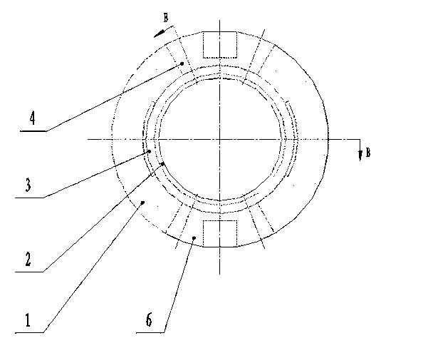
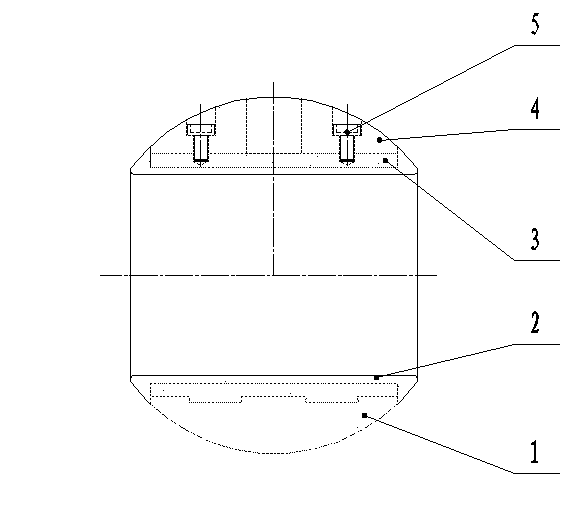
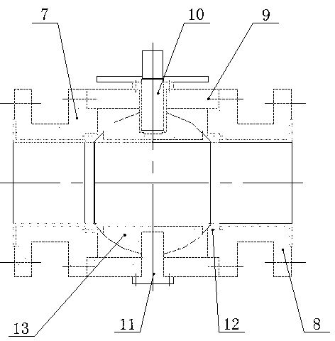
[0023] Example: such as figure 1 , figure 2 As shown, a medium and high pressure ceramic ball with resistance to erosion, wear and corrosion, as a ceramic ball 13 of a medium and high pressure ceramic ball valve with resistance to erosion, wear and corrosion, includes a steel cylinder 3, which is characterized in that: 3, a ceramic inner sleeve 2 is installed on the inner side, and a dovetail inlay groove is provided on the outer surface of the steel cylinder 3, and a dovetail inlay groove on the outer surface of the steel cylinder 3 is provided on the spherical ceramic insert 1. Dovetail inlay groove, the spherical ceramic insert 1 is closely combined with the steel cylinder 3 through the dovetail inlay groove, at the same time, the spherical ceramic insert 1 and the steel cylinder 3 are tightly bonded by an adhesive, and the steel cylinder 3 is set There are an upper valve stem seat 4 and a lower valve stem seat 6, and the upper valve stem seat 4 and the lower valve stem s...


PUM


Abstract

The invention relates to a scouring-resistant wear-resistant corrosion-resistant mid-high pressure ceramic ball valve for a medium conveying pipeline, and a manufacturing method of the scouring-resistant wear-resistant corrosion-resistant mid-high pressure ceramic ball valve. A scouring-resistant wear-resistant corrosion-resistant mid-high pressure ceramic ball body is used as a ceramic ball body of the ceramic ball valve. A ceramic inner bushing is mounted on the inner side of a steel cylinder through a hot shrinkage process. Dovetail inlaying grooves are formed in the outer side face of the steel cylinder and a spherical surface ceramic inlaying sheet respectively. The dovetail inlaying grooves are meshed with each other. The spherical surface ceramic inlaying sheet is tightly combined with the steel cylinder. The ceramic ball body is arranged in a middle valve body between a left valve body and a right valve body. An upper steel valve rod and a lower steel valve rod are both directly connected with a steel ball body through a valve rod base which is fastened through bolts. Two ceramic valve seats are arranged on the left valve body and the right valve body respectively. Therefore, perfect combination between the steel cylinder and a ceramic material is realized; the ceramic ball valve has the advantages of being resistant to scouring, wear, corrosion and high pressure; the service life of the ceramic ball valve is greatly prolonged; meanwhile, demands on mid-high pressure large-caliber ceramic ball valves can be satisfied.

Description

technical field [0001] The invention belongs to the technical field of ball valves, and in particular relates to a scour-resistant, wear-resistant, corrosion-resistant medium-high pressure ceramic ball valve for medium conveying pipelines and a manufacturing method thereof. Background technique [0002] The ball valve has the characteristics of compact structure, reliable sealing, simple structure, and convenient maintenance. The sealing surface and the spherical surface are often in a closed state, which is not easily eroded by the medium, easy to open and close quickly, and easy to operate and maintain. Therefore, ball valves are widely used in petroleum and chemical industries. , metallurgy, electric power, water conservancy, medicine and other fields. In addition, the ball valve has become one of the fastest-growing valves in recent years due to its advantages of small size, light weight, small consumables, small installation size, and small driving torque. The ball val...

Claims


Application Information

Patent Timeline
IPC IPC(8): F16K5/08F16K27/06
Inventor 杨涛张志宇王国胜
Owner 梅森阀门江苏有限公司
Learn More