
Orientation system for horizontal drill of deep-hole drill carriage

A deep-hole drilling rig and directional system technology, applied to the automatic control system of drilling, directional drilling, drilling equipment, etc., can solve the problems of inconvenient absolute space position and posture positioning, unreliable and unusable self-service positioning system, etc., to achieve Ensure data reliability and accuracy, improve real-time performance and scalability, and facilitate portability

Inactive Publication Date: 2015-05-20
JIANGYIN ZHONGKE MINING SAFETY TECH
View PDF5 Cites 0 Cited by
  • Summary
  • Abstract
  • Description
  • Claims
  • Application Information

AI Technical Summary

Problems solved by technology

Due to the special environment of coal mines, satellite positioning and radio navigation cannot be used on deep-hole drilling rigs. At present, the most commonly used horizontal drilling orientation system for deep-hole drilling rigs uses self-service positioning systems. The inertial unit is often used in self-service positioning systems. The advantage of the inertial unit is that it is independent of external information, but the complex magnetic field environment under the mine, the drift error of the inertial unit, and the difficulty in calibration will make the self-service positioning system unreliable or even unavailable; another type of horizontal drilling orientation system It is a total station, which is also a common tunnel construction monitoring instrument, but it is difficult to calibrate in coal mines, and the cost is high; there is also a horizontal drilling orientation system that is a laser orientation system, which is relatively reliable, but difficult to implement , and it is inconvenient to perform absolute space pose positioning of horizontal drilling

Method used


Image

  • Orientation system for horizontal drill of deep-hole drill carriage
  • Orientation system for horizontal drill of deep-hole drill carriage
  • Orientation system for horizontal drill of deep-hole drill carriage

Examples


Embodiment Construction

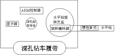
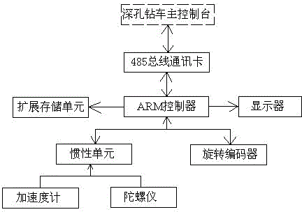
[0014] Such as figure 1 as shown, figure 1 It is a schematic diagram of the installation structure of the horizontal drilling orientation system of a deep hole drilling rig, including an inertial unit, a rotary encoder, a 485 bus communication card, an ARM controller and a display. The inertial unit, a rotary encoder, a 485 bus communication card, and an ARM controller All contain the same defined system bus interface, which are stacked and plugged together through 32 core pins. The 485 bus communication card contains a 485 bus communication interface. The inertial unit includes a UART serial bus interface and six sensors. The six Each sensor is divided into three orthogonally installed accelerometers and three orthogonally installed gyroscopes; the rotary encoder has a differential signal input interface, and the ARM controller has a switch signal input interface, a differential signal input interface, and a UART serial bus interface and display driver interface;

[0015] T...


PUM


Abstract

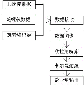
The invention relates to an orientation system for the horizontal drill of a deep-hole drill carriage. The orientation system comprises an inertial unit, a rotary encoder, a 485 bus communication card, an ARM controller and a display, wherein spatial position information is obtained by the inertial unit and the rotary encoder, and is then transmitted to the ARM controller; the ARM controller performs synchronous processing according to the received information, and then calculates the spatial position and the spatial drift angle of the horizontal drill respectively; two-ply Kalman filtering data fusion algorithm are performed respectively to obtain true and reliable position data of the horizontal drill, which is then stored in the expansion memory; the horizontal drill position information transmission is performed passively or actively according to instruction of a deep hole drill carriage console; and the information is shown on the display in a real-time manner. The orientation system for the horizontal drill of the deep-hole drill carriage is accurate in real-time localization and reliable in data, and has good feasibility and is low in manufacture cost.

Description

technical field [0001] The invention relates to a horizontal drilling orientation system of a deep hole drilling vehicle. Background technique [0002] The horizontal drilling directional system of deep hole drilling rigs is widely used in coal mine deep hole drilling rigs. Due to the special environment of coal mines, satellite positioning and radio navigation cannot be used on deep-hole drilling rigs. At present, the most commonly used horizontal drilling orientation system for deep-hole drilling rigs uses self-service positioning systems. The inertial unit is often used in self-service positioning systems. The advantage of the inertial unit is that it is independent of external information, but the complex magnetic field environment under the mine, the drift error of the inertial unit, and the difficulty in calibration will make the self-service positioning system unreliable or even unavailable; another type of horizontal drilling orientation system It is a total station...

Claims


Application Information

Patent Timeline
Patent Type & Authority Patents(China)
IPC IPC(8): E21B7/04E21B47/022E21B44/00
Inventor 余意尚留记李逊
Owner JIANGYIN ZHONGKE MINING SAFETY TECH
Learn More