
Self-locking clamping device based on thermally induced linear expansion

A self-locking clip and linear expansion technology, applied in the field of mechanical clamping, can solve problems such as noise pollution, environmental pollution, energy consumption, etc., and achieve the effects of reducing energy conversion links, reducing use costs, and improving utilization.

Active Publication Date: 2013-09-11
KUNSHAN JER ELECTRONICS TECH
View PDF5 Cites 3 Cited by
  • Summary
  • Abstract
  • Description
  • Claims
  • Application Information

AI Technical Summary

Problems solved by technology

[0003] 1. Hydraulic fixtures need to provide pressure oil pumps, and pneumatic fixtures need to provide compressed air air compressors. The driving source is complicated, large in size and high in cost.
[0004] 2. There are many energy conversion and control links, large energy loss, low energy utilization rate, and low clamping efficiency, resulting in a relative increase in use costs
[0005] 3. There is a high-speed rotating mechanical transmission device, and the noise pollution is relatively serious
[0006] 4. The hydraulic transmission fixture has the problem of oil leakage, which is easy to cause environmental pollution
[0007] 5. In order to maintain a continuous clamping effect, resulting in continuous energy consumption, the effective utilization of energy is low
However, there are certain defects in the traditional area effect travel amplification device
When determining the magnification, if the size of the driving piston is limited, the size of the output piston will also be fixed, and the size of the output piston rod must be sacrificed in order to place the return spring in the rod cavity, which may cause the size of the piston rod to be too small , the rigidity is poor, resulting in the instability and damage of the piston rod; conversely, if the rigidity of the output piston rod is guaranteed, the size of the output piston must be enlarged, and the size of the driving piston will also increase accordingly, so that the entire device is too bulky and the structure complex and expensive

Method used


Image

  • Self-locking clamping device based on thermally induced linear expansion
  • Self-locking clamping device based on thermally induced linear expansion
  • Self-locking clamping device based on thermally induced linear expansion

Examples


Embodiment 1

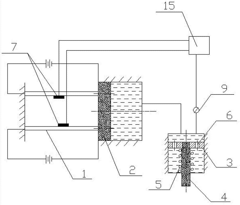
[0044] Such as figure 1 As shown, the heat-sensitive drive components are two heat-sensitive transmission rods 1 symmetrically arranged, one end of the heat-sensitive transmission rod 1 is fixed, the other end is connected to the driving piston 2, and the temperature control component is electrically connected to the heat-sensitive transmission rod. By energizing the circuit, the heat-sensitive transmission rod heats up under the action of electric heating or naturally heats up after cooling. During the heating process, the heat-sensitive transmission rod gradually elongates, and gradually pushes the driving piston forward under the action of the heat-sensitive transmission rod. Move, and then push the piston rod down to press the workpiece; when it is released, stop heating or cooling, so that the heat-sensitive transmission rod shrinks and resets, and the output piston and piston rod reset under the action of the return spring 5.

[0045] Wherein, the number of the heat-sens...

Embodiment 2

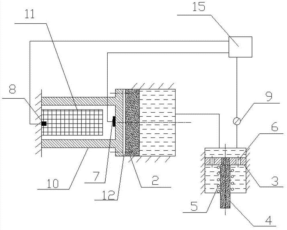
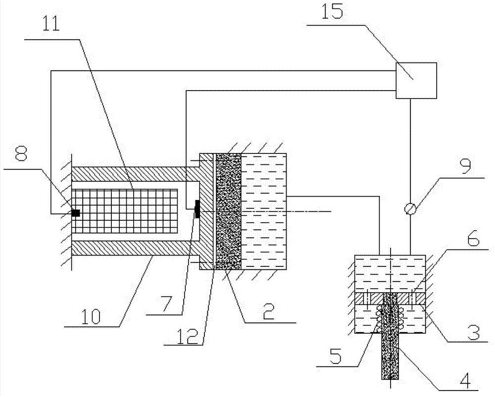
[0049] Such as figure 2 , 3 As shown, the heat-sensitive driving component is a hollow thin-walled tube 10 , and a semiconductor heating / refrigerating element 11 is arranged inside the hollow thin-walled tube. One end of the hollow thin-walled tube 10 is fixed, and the other end is connected to the driving piston 2 .

[0050] A heat insulating pad 12 is provided at the joint between the hollow thin-walled tube and the driving piston to prevent the hollow thin-walled tube from overheating and damaging the driving piston.

[0051] By using the semiconductor heating / cooling fast conversion technology to act on the hollow thin-walled tube, due to the heat-induced linear expansion of the material, the size of the material will increase approximately linearly with the increase of temperature, and vice versa. That is, in the semiconductor cooling state, the material shrinks, and in the heating state, the material elongates. Therefore, controllable two-way micro-displacement can be...


PUM


Abstract

The invention discloses a self-locking clamping device based on thermally induced linear expansion. The self-locking clamping device comprises a micro-drive device and a travel amplifying device, the micro-drive device is provided with a thermosensitive drive component made of temperature sensitive materials, and a hear source is provided by a rapid semiconductor refrigerating / heating technology. The differential travel amplifying device with internal backflow area is used for amplifying travel, and the size of an output piston is not limited while amplification coefficient is ensured. When in operation, the self-locking clamping device is set in an original refrigerating state, the piston is driven to move by the elongation of the thermosensitive drive component in the room temperature recovery process, a workpiece is clamped, and long-term clamping is kept by temperature potential energy accumulated in the room temperature state. The self-locking clamping device is compact and simple in structure, pollution-free, green, environment-friendly, simple in operating mode, low in energy consumption and high in energy utilization rate, only two times of one-way refrigeration are needed in one operating process of clamping and loosening, and clamping is kept by the temperature potential energy without continuously supplying energy.

Description

technical field [0001] The invention belongs to the technical field of mechanical clamping, and in particular relates to a self-locking clamping device based on thermally induced linear expansion. Background technique [0002] Fixtures play an important role in the manufacturing industry, can improve production efficiency, ensure labor safety, and are widely used. At present, most of the clamps widely used are hydraulic or pneumatic clamping devices, but the traditional clamping has obvious shortcomings, as follows: [0003] 1. The hydraulic clamp needs to provide a pressure oil pump, and the pneumatic clamp needs to provide an air compressor for compressing air. The driving source is complicated, large in size and high in cost. [0004] 2. There are many energy conversion and control links, large energy loss, low energy utilization rate, and low clamping efficiency, resulting in a relative increase in use costs. [0005] 3. There is a high-speed rotating mechanical transm...

Claims


Application Information

Patent Timeline
Patent Type & Authority Applications(China)
IPC IPC(8): B25B11/00
Inventor 王传洋李知瑶钟康民
Owner KUNSHAN JER ELECTRONICS TECH
Learn More