
Top Roller Clamping Device

A clamping device and top roller technology, which is applied in the direction of grinding workpiece supports, etc., can solve the problems of low work efficiency and high labor intensity of manual loading and unloading of top rollers

Active Publication Date: 2016-02-10
WUJIANG WANGONG ELECTROMECHANICAL EQUIP
View PDF6 Cites 0 Cited by
  • Summary
  • Abstract
  • Description
  • Claims
  • Application Information

AI Technical Summary

Problems solved by technology

In the existing roller grinding machine, the top rollers are manually loaded and unloaded, and the work efficiency of manual loading and unloading of the top rollers is low and the labor intensity is high

Method used


Image

  • Top Roller Clamping Device
  • Top Roller Clamping Device
  • Top Roller Clamping Device

Examples


Embodiment Construction

[0025] The present invention will be described in detail below with reference to the accompanying drawings and in combination with embodiments.

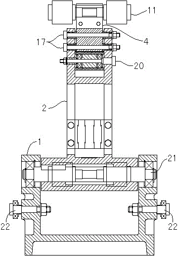
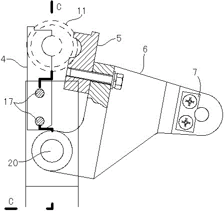
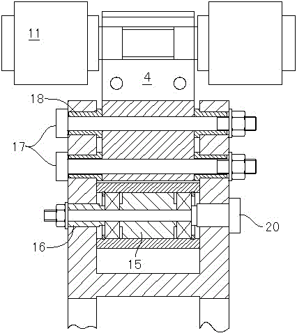
[0026] refer to image 3 , Figure 4 As shown, the static jaw 4 is installed on the tong frame 2 with two static jaw pin shafts 17 and axle sleeves 18, and the static jaw pin shaft 17 is fastened on the tong frame 2 by nuts; Fastened on the rocker 6, the rocker 6 is installed on the clamp frame 2 through the bushing 15, the bearing spacer 16, the rocker shaft 20 and the miniature bearing.

[0027] When the piston rod of the rocker cylinder 25 is withdrawn, the opening angle A between the static jaw 4 and the moving jaw 5 is greater than 10°30′.

[0028] The clamp frame cylinder 26 is connected with the clamp frame 2 through the joint bearing 14, and the rocking block cylinder 25 is connected with the described rocking block 6 through another joint bearing 14; the piston rod of the clamp frame cylinder 26, the rocking block cylinder...


PUM


Abstract

The invention discloses a roller clamping device comprising an 'L'-shaped clamp frame. A corner of the clamp frame is hinged and fixed, a roller is clamped at the top end of the clamp frame, the side end of the clamp frame is pushed through a clamp frame cylinder so as to enable the vertically arranged clamp frame to rotate to be horizontal, a roller driving device drives the roller to mill on a grinding machine on one side. After milling, the clamp frame cylinder withdraws, the clamp frame rotates to a vertical position, and automation of rolling milling is realized.

Description

technical field [0001] The invention relates to a mechanism for clamping top rollers, in particular to a top roller clamping device for clamping top rollers in a top roller grinding machine of cotton and wool spinning equipment to realize automatic grinding of top rollers. Background technique [0002] After the spinning frame has been used for a period of time, due to the wear on the surface of the top rollers, the surface of the top rollers must be ground to make the top rollers meet the requirements for use. In the existing roller grinding machine, the top rollers are manually loaded and unloaded, and the manual loading and unloading of the top rollers has low work efficiency and high labor intensity. Contents of the invention [0003] The object of the present invention is to overcome the above problems in the prior art, and provide a top roller clamping device to realize the automation of top roller grinding. [0004] In order to achieve the above-mentioned technical...

Claims


Application Information

Patent Timeline
Patent Type & Authority Patents(China)
IPC IPC(8): B24B41/06
Inventor 周平郑志刚
Owner WUJIANG WANGONG ELECTROMECHANICAL EQUIP
Learn More