Transmission mechanism used for outdoor high-voltage vacuum switch

A technology of vacuum switch and transmission mechanism, which is applied in the direction of high voltage/high current switch, high voltage air circuit breaker, electric switch, etc. It is not easy to waterproof and other problems, and achieves the effect of simple structure, good interchangeability and regular shape

Active Publication Date: 2015-07-01
SHENYANG HUADE HIGH TECH ELECTRIC CO LTD +1
View PDF5 Cites 0 Cited by
  • Summary
  • Abstract
  • Description
  • Claims
  • Application Information

AI Technical Summary

Problems solved by technology

The transmission mechanism used for high-voltage switches in the prior art is a rotary transmission mechanism, that is, a crank arm shaft with a hexagonal hole is installed on a long hexagonal main shaft, and the crank arm shaft and the output shaft of the spring operating mechanism Connected by cylindrical pins, three sets of four-bar linkage mechanisms with the hexagonal spindle as the support point are installed in the independent frame at an equidistant axial distance on the hexagonal spindle. When the spring operating mechanism performs opening and closing operations, The shaft rotates the hexagonal main shaft, and then drives three sets of four-bar linkages to realize the opening and closing operation of the interrupter. Synchronous Periodicity of Interrupter Opening and Closing

Method used


Image

  • Transmission mechanism used for outdoor high-voltage vacuum switch
  • Transmission mechanism used for outdoor high-voltage vacuum switch
  • Transmission mechanism used for outdoor high-voltage vacuum switch

Examples


Embodiment Construction

[0037] Specific embodiments of the present invention are provided below in conjunction with the accompanying drawings.

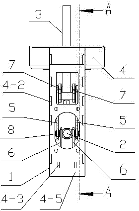
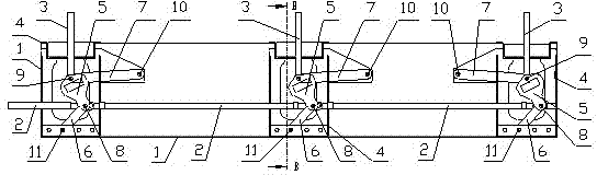
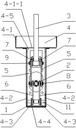
[0038] As shown in the accompanying drawings, the present invention comprises three fixed mounts 4, and each fixed mount 4 is equipped with 2 connecting plates 5, as Figure 4 As shown, the connecting plate 5 is processed with a first pin connecting hole 5-1, a second pin connecting hole 5-2 and a process hole 5-3, as Figure 5 to Figure 7 As shown, the fixed frame 4 has a fixed seat 4-1 used to connect with the tank body or cabinet in the switchgear, and two outer fixed plates 4-2 are welded after plugging under the fixed seat 4-1. , weld the base plate 4-4 after plugging the bottoms of the 2 outer fixing plates 4-2, weld the 2 inner fixing plates 4-3 after the insertion of the base plate 4-4, and weld the outer fixing plate 4-2 and the inner fixing plate 4 -3 and base plate 4-4 are plugged and welded with 2 side plates 4-5, and a transmission rod passing...


PUM


Abstract

The invention discloses a transmission mechanism used for an outdoor high-voltage vacuum switch, which overcomes the defects that the existing rotary transmission mechanism is complex in structure, large in size, high in cost, low in efficiency and difficult in water resistance, and the state that the switching on and opening of a three-phase arc extinguish chamber have the same period cannot be ensured, and is characterized in that two mounting plates are arranged on each fixed frame which is connected with the connecting plates and a transmission rod through a first hinge pin and is connected with the connecting plates and a conveying rod through a second hinge pin; the other end of each transmission rod supporting plate is connected and fixed with a third hinge pin on each fixed frame; the other end of each conveying rod supporting plate is connected and fixed with a fourth hinge pin on each fixed frame; when the conveying rod is pushed rightwards, the opening of the arc extinguish chamber is realized; when the conveying rod is pushed leftwards, the switching on of the arc extinguish chamber is realized; and a rain cover is arranged on the outer sides of the fixed frames. The transmission mechanism has the beneficial effects that the structure is simple, the size is small, the cost is low, the water-proof effect is good, the efficiency is high, the switching on and the opening of the three-phase arc extinguish chamber are guaranteed to have the same period, each fixed frame is an independent unit, the exchangeability is good, the standard production is realized, and the mounting, repair and replacement are convenient.

Description

technical field [0001] The invention belongs to the technical field of high-voltage electrical appliances, and in particular relates to a transmission mechanism for an outdoor high-voltage vacuum switch. Background technique [0002] The transmission mechanism is an important mechanical component on the switchgear and plays a very important role in the entire power supply system. The transmission mechanism used for high-voltage switches in the prior art is a rotary transmission mechanism, that is, a crank arm shaft with a hexagonal hole is installed on a long hexagonal main shaft, and the crank arm shaft and the output shaft of the spring operating mechanism Connected by cylindrical pins, three sets of four-bar linkage mechanisms with the hexagonal spindle as the support point are installed in the independent frame at an equidistant axial distance on the hexagonal spindle. When the spring operating mechanism performs opening and closing operations, The shaft rotates the hex...

Claims


Application Information

Patent Timeline
Patent Type & Authority Patents(China)
IPC IPC(8): H01H33/666
Inventor 侯亚平张交锁陈涛国世峥
Owner SHENYANG HUADE HIGH TECH ELECTRIC CO LTD
Why Eureka
Try Eureka