Handle operation mechanism with self-locking device used on isolation switch

A technology of isolating switch and self-locking device, applied in electrical switches, electrical components, circuits, etc., can solve problems such as incorrect closing, affecting product service life, and complex mechanism.

Active Publication Date: 2015-05-06
DELIXI ELECTRIC
View PDF7 Cites 0 Cited by
  • Summary
  • Abstract
  • Description
  • Claims
  • Application Information

AI Technical Summary

Problems solved by technology

[0002] A general isolating switch includes an operating mechanism and an energy storage mechanism. The operating mechanism usually includes an operating handle and a contact support, and the isolation position requires additional instructions. The energy storage mechanism is mainly a spring. When the power is supplied, the operating handle drives the contact support to separate the moving contacts, and the energy storage mechanism keeps the handle in the disconnected position, and there are special instructions to show that the isolating switch is in the disconnected position. This kind of mechanism is generally more complicated, and the dimensional accuracy of the parts is required to be higher. , so the cost of the product is also very good, and the spring will be fatigued, which will affect the service life of the product
[0003] In addition, there is also an isolating switch without an energy storage mechanism, such as the patent No. 200720193959.7 "Operating Mechanism for Isolating Power Supply", which realizes two This structure simplifies the complex and display problems of using the energy storage mechanism, but there are also hidden dangers of unsafety: especially if the operator does not manually buckle the latch When the hook is connected to the engaging part, it is easy to touch the handle and cause it to close by mistake, which is very dangerous

Method used


Image

  • Handle operation mechanism with self-locking device used on isolation switch
  • Handle operation mechanism with self-locking device used on isolation switch
  • Handle operation mechanism with self-locking device used on isolation switch

Examples


Embodiment Construction

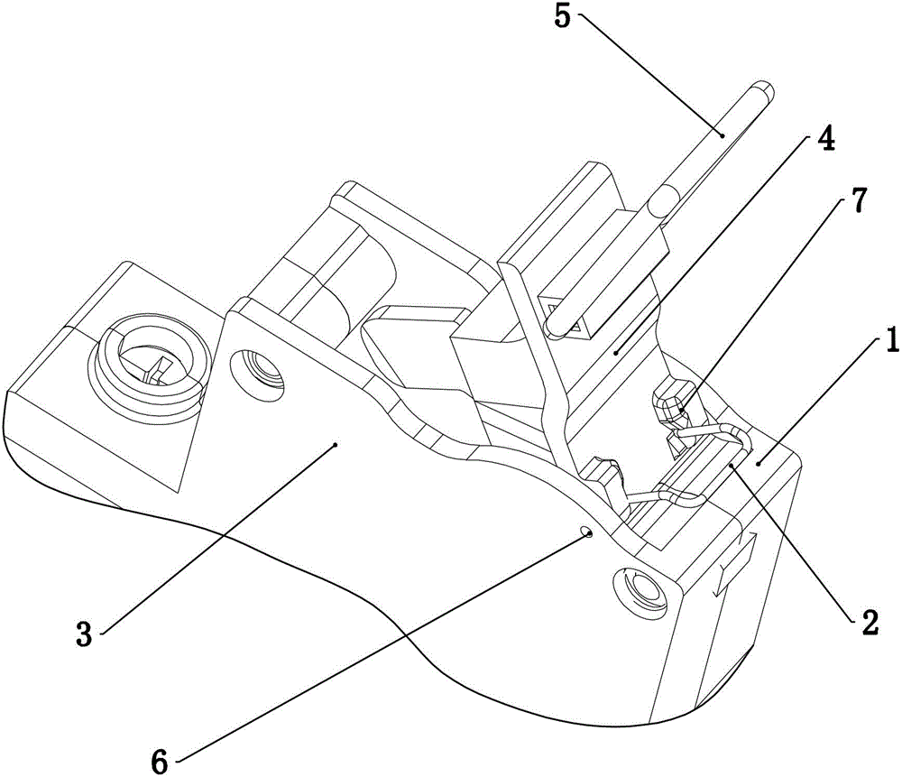
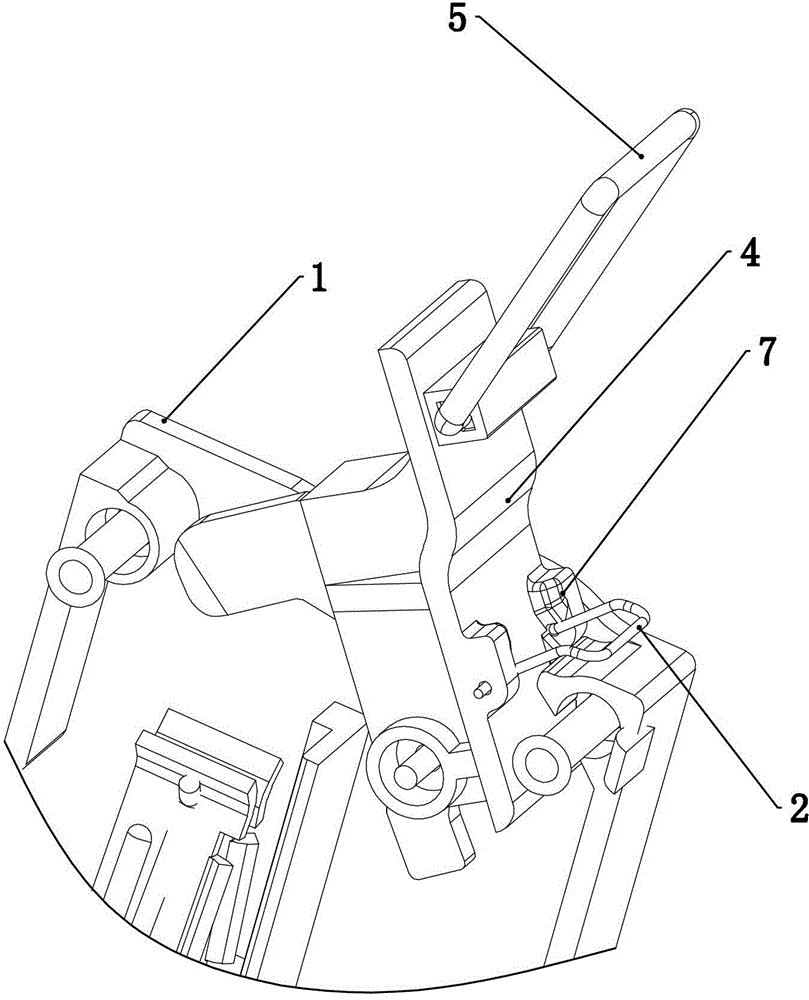
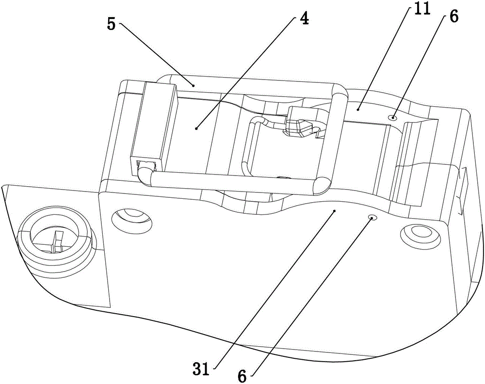
[0017] Such as figure 1 , figure 2 , image 3 , Figure 4 and Figure 5 As shown, a handle operating mechanism with a self-locking device used on a disconnector includes an insulating handle 4 hingedly arranged on the base 1 and cover 3 of the disconnector, and the inner side of the handle 4 is provided with a moving contact , the outer back of the handle 4 is provided with an elastic member 2, specifically as long as the elastic member 2 is firmly arranged on the handle 4, at least one end of the elastic member 2 is an extension end that can automatically extend along the width direction of the handle 3 21. The elastic part 2 is provided with a force-receiving part 22 that can be pressed by a tool or hand to reset the extended end. Lock the matching lock hole 6 or lock groove, and the stretching end 21 of the elastic part automatically stretches and slides into the lock hole 6 or lock groove after the isolation switch opening handle 4 is tilted to form an automatic conta...


PUM


Abstract

The invention relates to a handle operation mechanism of an isolation switch in a low-voltage electrical apparatus, and particularly relates to an operation mechanism provided with a self-locking device on a handle. The adopted technology is as follows: a handle operation mechanism with a self-locking device used on an isolation switch is characterized in that the outer back surface of the handle is provided with an elastic member; the elastic member is at least provided with an extending end of which one end can be automatically extended in the width direction of the handle; the elastic member is provided with a stress part capable of being pressed by a tool or a hand so as to reset the extending end; a base and / or a cover of the isolation switch are / is provided with a locking hole or a locking groove in locking match with the extending end of the elastic member. Through the above scheme, problems in the prior art are overcome, and a novel handle operation mechanism capable of locking the handle after the isolation switch is powered off is provided.

Description

technical field [0001] The invention relates to a handle operating mechanism of an isolating switch of a low-voltage electrical appliance, in particular to an operating mechanism provided with a self-locking device on the handle. Background technique [0002] A general isolating switch includes an operating mechanism and an energy storage mechanism. The operating mechanism usually includes an operating handle and a contact support, and the isolation position requires additional instructions. The energy storage mechanism is mainly a spring. When the power is supplied, the operating handle drives the contact support to separate the moving contacts, and the energy storage mechanism keeps the handle in the disconnected position, and there are special instructions to show that the isolating switch is in the disconnected position. This kind of mechanism is generally more complicated, and the dimensional accuracy of the parts is required to be higher. , so the cost of the product i...

Claims


Application Information

Patent Timeline
Patent Type & Authority Patents(China)
IPC IPC(8): H01H9/20H01H21/22
Inventor 陈百胜
Owner DELIXI ELECTRIC
Why Eureka
Try Eureka