
Liquid crystal display panel and driving method thereof

A technology of liquid crystal display panels and driving methods, applied in static indicators, nonlinear optics, instruments, etc., which can solve the problems of whitening of liquid crystal panels, long waiting time for opening, abnormal color gradients, etc.

Active Publication Date: 2013-09-04
XIAMEN TIANMA MICRO ELECTRONICS
View PDF4 Cites 8 Cited by
  • Summary
  • Abstract
  • Description
  • Claims
  • Application Information

AI Technical Summary

Problems solved by technology

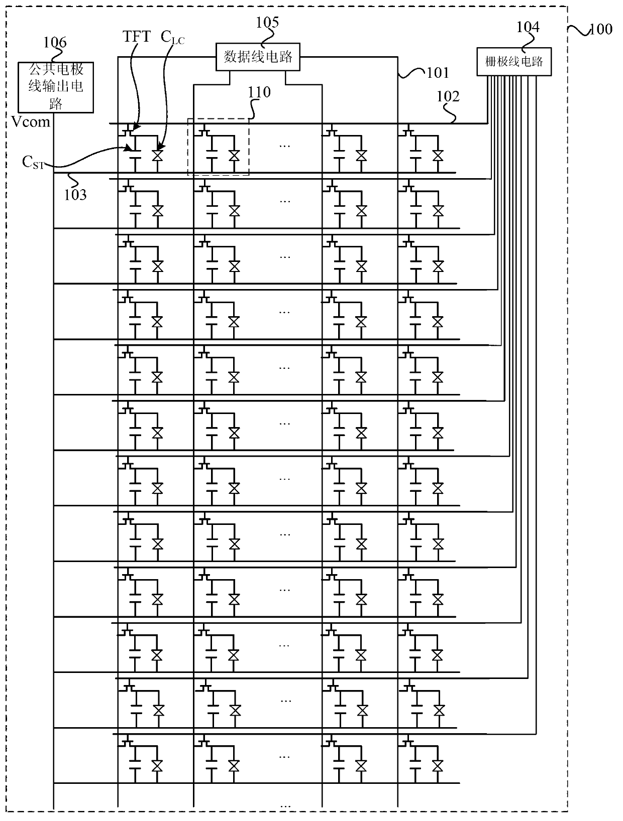
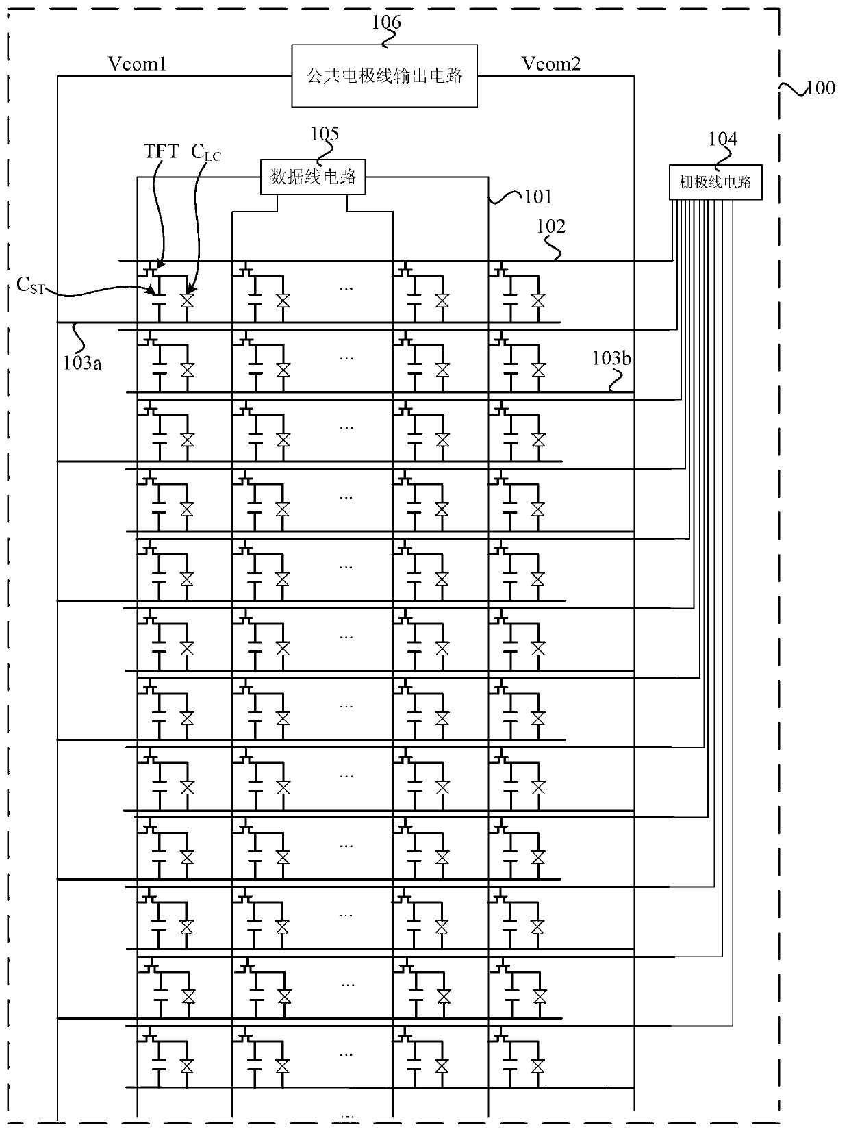
However, image 3 The structure of the liquid crystal panel 100 shown has a problem: at the beginning of a frame, the first common voltage Vcom1 and the second common voltage Vcom2 undergo an inversion, and then each gate line circuit 104 is sequentially connected to the gate line 102 connected to it. When the pixel unit 110 of a row outputs a gate voltage, the TFT of the pixel unit in this row is turned on, and the pixel units 110 in other rows are turned off, and each gate line sequentially outputs a gate voltage from top to bottom, and each row of pixel units 100 from top to bottom Turn on sequentially, so within a frame time, the pixel unit 110 in the next row waits for a longer time to turn on
Moreover, the phenomenon of leakage of electricity from top to bottom of the entire panel becomes more and more serious, and the drift of the gray scale voltage caused by the phenomenon of leakage becomes more and more serious, which in turn leads to whitening, blackening, and abnormal color gradients of the entire liquid crystal panel 100 from top to bottom.

Method used


Image

  • Liquid crystal display panel and driving method thereof
  • Liquid crystal display panel and driving method thereof
  • Liquid crystal display panel and driving method thereof

Examples


Embodiment Construction

[0033] In order to make the content of the present invention clearer and easier to understand, the content of the present invention will be further described below in conjunction with the accompanying drawings. Of course, the present invention is not limited to this specific embodiment, and general replacements known to those skilled in the art are also covered within the protection scope of the present invention.

[0034] Secondly, the present invention is described in detail by means of schematic diagrams. When describing the examples of the present invention in detail, for the convenience of explanation, the schematic diagrams are not partially enlarged according to the general scale, which should not be used as a limitation of the present invention.

[0035] Figure 5 It is a schematic structural diagram of a liquid crystal display panel in an embodiment of the present invention. Such as Figure 5 As shown, the present invention provides a liquid crystal display panel 10...


PUM


Abstract

The invention provides a liquid crystal display panel and a driving method of the liquid crystal display panel. The liquid crystal display panel comprises a plurality of pixel units which are arranged in an array mode, a first common electrode wire and a second common electrode wire, wherein more than two successive rows of successive pixel units form one set, and multiple sets of pixel units are formed. Any two adjacent rows of pixel units in each set are respectively connected with the first common electrode wire and the second common electrode wire, the last row of pixel units of the former set of the two adjacent sets and the first row of pixel units of the later set of the two adjacent sets are connected to the same common electrode wire, the common voltage reversing cycle of the first common electrode wire and the common voltage reversing cycle of the second common electrode wire are the same and mutually opposite in phase, and every time one set of the pixel units is scanned, the common voltage reversing cycle of the first common electrode wire and the common voltage reversing cycle of the second common electrode wire are reversed once. The liquid crystal display panel and the driving method of the liquid crystal display panel can avoid the phenomena of whitening, blackening and abnormal gradual change of colors, and can lower the power consumption.

Description

technical field [0001] The invention relates to flat panel display technology, in particular to a liquid crystal display panel and a driving method thereof. Background technique [0002] TFT (Thin Film Transistor, Thin Film Field Effect Transistor) means that each liquid crystal pixel unit point on the liquid crystal display is driven by a thin film transistor integrated behind it, so that a high-speed, high-brightness, high-contrast display screen can be achieved Information, the common TFT-LCD (Thin Film Transistor Liquid Crystal Display) is one of the most liquid crystal displays. [0003] Conventional liquid crystal display devices display images by controlling the rotation of liquid crystal molecules using an electric field. Such as figure 1 As shown, a conventional liquid crystal display device generally includes: a liquid crystal panel 100, a plurality of data lines 101 formed on the liquid crystal panel 100, a plurality of gate lines 102, a common electrode line 10...

Claims


Application Information

Patent Timeline
IPC IPC(8): G02F1/1362G02F1/133G09G3/36
Inventor 张成凤李元曾章和李嘉灵
Owner XIAMEN TIANMA MICRO ELECTRONICS
Learn More