Stress testing device and stress concentration testing method based on speckle interference principle

A technology of stress testing and speckle interference, which is applied in the fields of materials science, optics and mechanics, and can solve problems such as poor flexibility, complicated and complicated process of adjusting the optical path, and inability to measure actual components.

Inactive Publication Date: 2013-09-04
HARBIN INST OF TECH
View PDF6 Cites 9 Cited by
  • Summary
  • Abstract
  • Description
  • Claims
  • Application Information

AI Technical Summary

Problems solved by technology

[0005] In order to solve the problem that the existing laser speckle technology has a cumbersome and complicated process of adjusting the optical path, and the flexibility is...

Method used


Image

  • Stress testing device and stress concentration testing method based on speckle interference principle
  • Stress testing device and stress concentration testing method based on speckle interference principle
  • Stress testing device and stress concentration testing method based on speckle interference principle

Examples


specific Embodiment approach 1

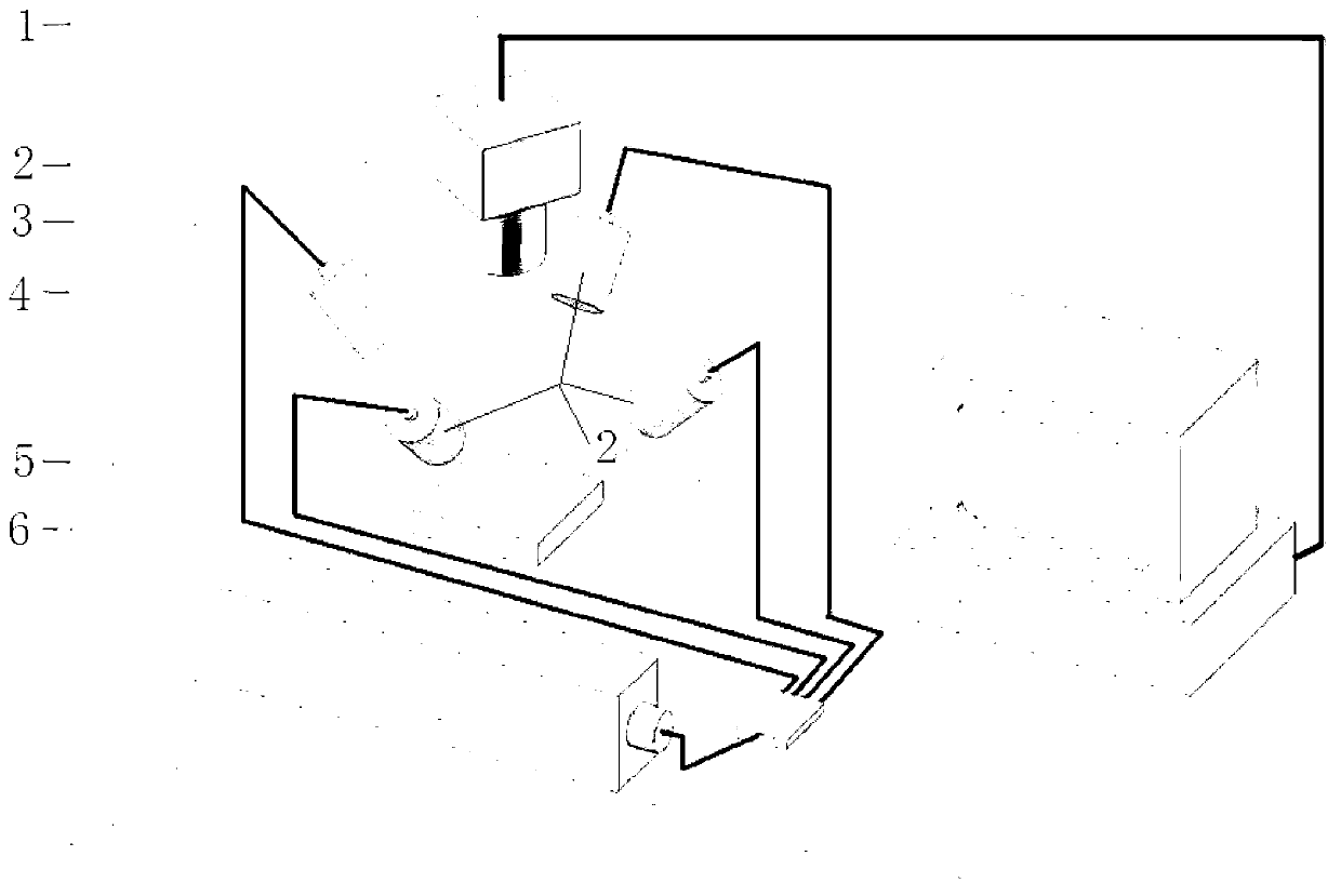
[0064] Specific implementation mode 1. Combination figure 1 This embodiment is described in detail. The stress testing device based on the principle of speckle interference described in this embodiment includes a digital CCD camera 1, four collimating beam expanders 2, a single-mode laser 3, a fiber coupler 4, and a fiber beam splitter 5 and computer 6,

[0065] After the laser light emitted by the single-mode laser 3 is coupled by the fiber coupler 4, it is sent to the fiber beam splitter 5 through the optical fiber. The optical fiber is sent to four collimating beam expanders 2,

[0066] The four collimated parallel laser beams emitted by the four collimated beam expanders 2 irradiate the surface of the test piece to form a speckle field,

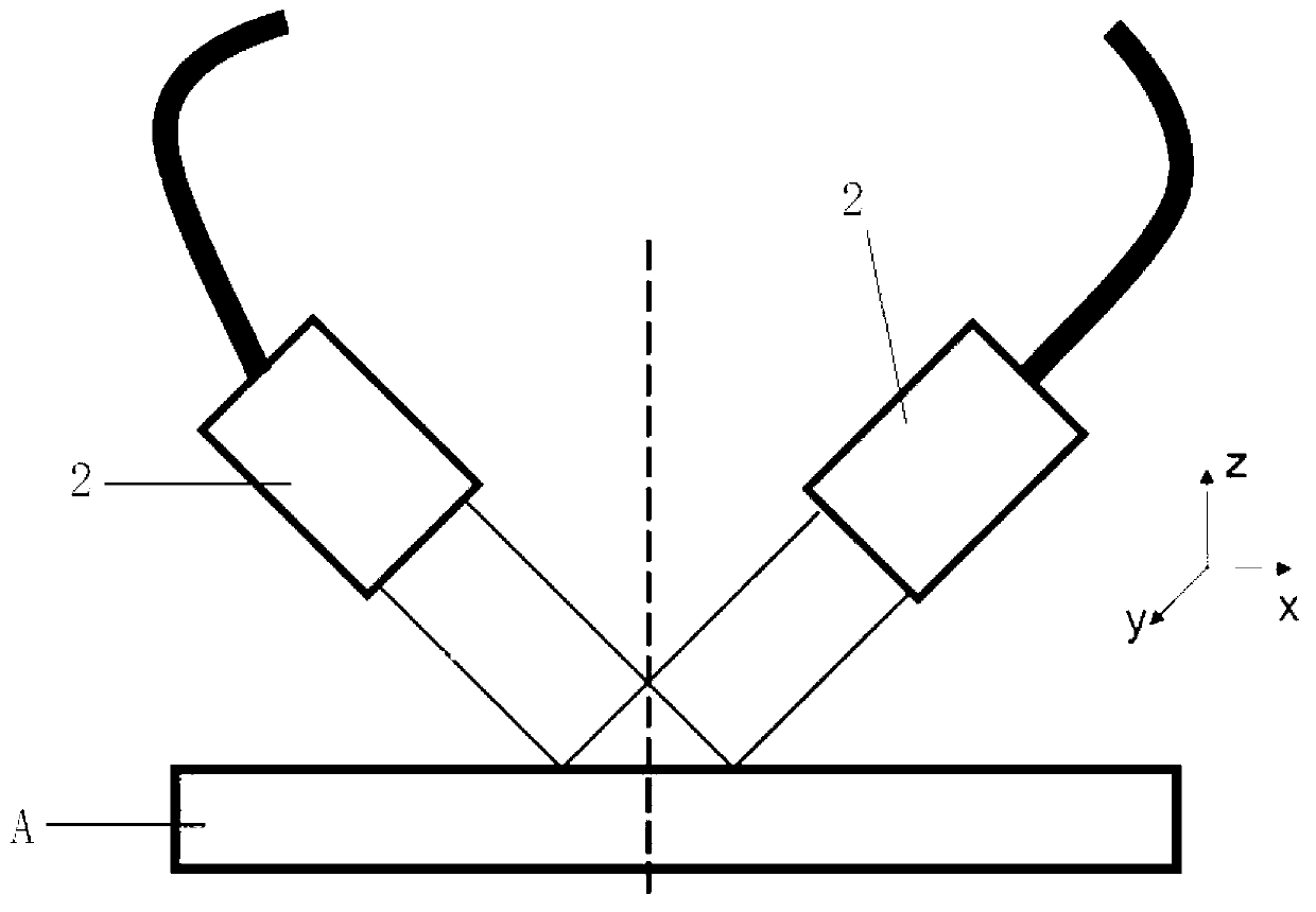
[0067] The four collimating beam expanders 2 are symmetrically distributed in pairs, and the four collimating beam expanders 2 are divided into two groups, each group includes two collimating beam expanders 2, and the two collimating be...

specific Embodiment approach 2

[0078] Specific embodiment two, the difference between this embodiment and the stress testing device based on speckle interference principle described in specific embodiment one is that the digital CCD camera 1 adopts an industrial camera with 1.3 million pixels, and the lens of the camera is Microscope magnifying lens.

specific Embodiment approach 3

[0079] Embodiment 3. The difference between this embodiment and the stress testing device based on the principle of speckle interference described in Embodiment 1 is that the single-mode laser 3 is a single-mode He-Ne laser.

[0080] The single-mode helium-neon laser described in this embodiment is a single-mode helium-neon laser with a power of 40mW


PUM


Abstract

The invention relates to a stress testing device and stress concentration testing method based on the speckle interference principle. The stress testing device and stress concentration testing method based on the speckle interference principle solves the problems that according to an existing laser speckle technology, a process for regulation a light path is cockamamie and complex, flexibility is poor, and the existing laser speckle technology can be only used for laboratory measurement analysis and cannot carry out on-site measurement on actual components with large sizes and complex space shapes. Four collimation beam expanding mirrors are adopted in the stress testing device and stress concentration testing method and are arranged on the surface of a tested piece symmetrically, two beams of collimation parallel laser are obtained, a digital CCD camera is used for collecting four speckle field images loaded before and after deformation respectively through control of on-off of four paths of light, and the computer digital picture processing technique is adopted to obtain displacement distribution in two orthogonal directions to further obtain distributed information of stress states of a tested area. The stress testing device and stress concentration testing method is applied to crossing fields of materials science, optics and mechanics.

Description

technical field [0001] The invention relates to the cross fields of material science, optics and mechanics, in particular to a stress test device and a stress concentration test method based on the principle of speckle interference. Background technique [0002] Laser speckle interferometry, also known as electronic speckle interferometry, is an optical-based, full-field, non-contact non-destructive measurement and detection technology. When a beam of coherent light is irradiated on a flat and rough reflective surface, the diffusely reflected light waves are superimposed on each other, forming a speckle-like distribution of light and dark, that is, the speckle field. The speckle field records the geometric information of the surface of the object. Using appropriate optical path and processing technology, the surface displacement, strain, roughness, three-dimensional shape, etc. can be measured and detected. [0003] At present, the commonly used stress measurement method is...

Claims


Application Information

Patent Timeline
IPC IPC(8): G01L1/04
Inventor 刘雪松潘海博闫忠杰尚哲王帅丽王强李书奇王为董志波方洪渊
Owner HARBIN INST OF TECH
Why Eureka
Try Eureka