Novel transmission device of combined machine

A transmission device and combination machine technology, which is applied to transmission device parts, mechanical equipment, belts/chains/gears, etc., can solve the problem that the concentricity and runout of the upper and lower dies cannot be guaranteed, and the concentricity and ellipse of the power shaft cannot be guaranteed. In order to reduce the vibration, increase the concentricity and stabilize the rotation

Active Publication Date: 2013-09-04
ZHOUSHAN BODA MACHINERY MFG
View PDF5 Cites 0 Cited by
  • Summary
  • Abstract
  • Description
  • Claims
  • Application Information

AI Technical Summary

Problems solved by technology

[0003] For detailed drive lines, see figure 2 As shown, however, the above transmission system has the following problems. First, the power shaft passes through the upper deep groove ball bearing (radial bearing, which mainly bears radial load) and the lower thrust ball bearing (axial bearing, which can only bear the radial load). Bear axial load) to control, the power shaft at this time is single-point positioning, when the concentricity changes, the thrust bearing below is easily damaged, and the concentricity and runout of the upper and lower dies cannot be guaranteed, so that The quality of the product has declined
Second, the transmission route is long, and the errors of the transmission parts accumulate, so that the rotation of the power shaft cannot guarantee the concentricity and ellipticity
Third, the rotating cylinder is too large. When the machine malfunctions and needs to be stopped, the inertia is too large, causing damage to the machine

Method used


Image

  • Novel transmission device of combined machine
  • Novel transmission device of combined machine
  • Novel transmission device of combined machine

Examples


Embodiment Construction

[0016] In order to make the object, technical solution and advantages of the present invention clearer, the present invention will be further described in detail below in conjunction with the accompanying drawings and examples. However, the examples given are not intended to limit the present invention.

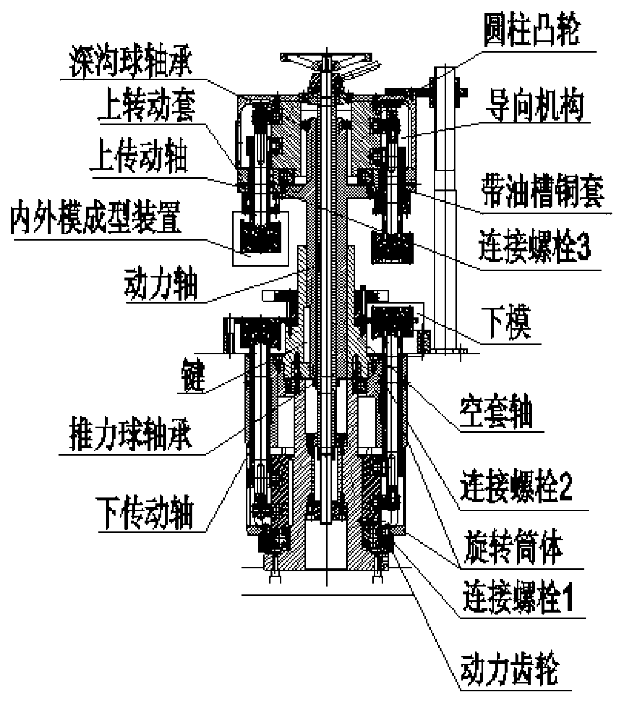
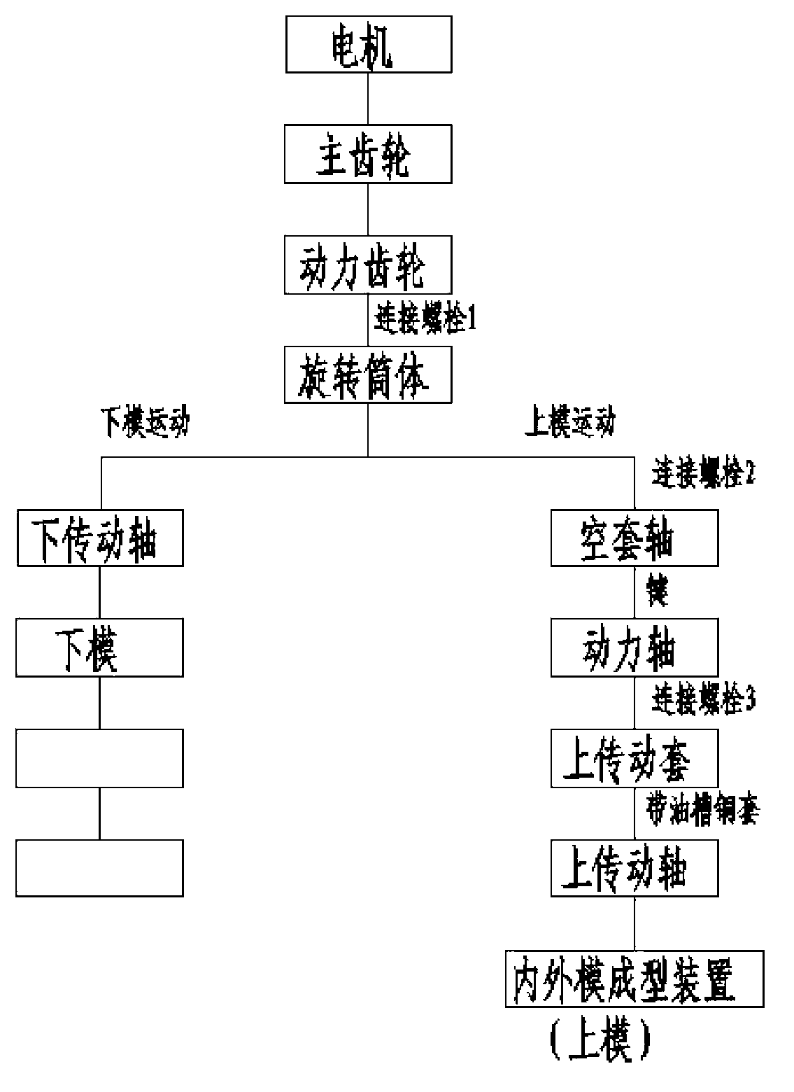
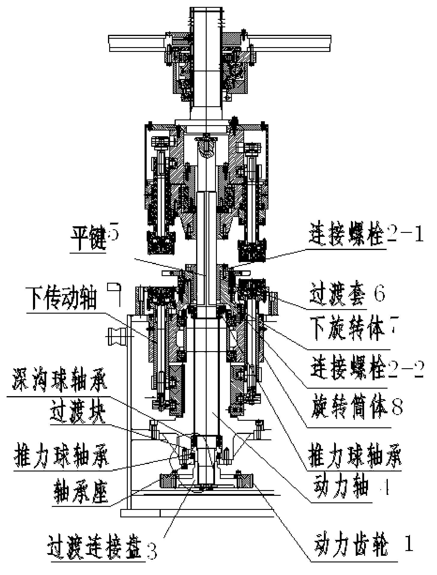
[0017] Such as image 3 As shown, the present invention provides a new type of transmission device for a combination machine, including a power gear (1), a connecting bolt (2), a transition connection plate (3), a power shaft (4), a flat key (5), a transition sleeve ( 6), the lower rotating body (7), the rotating cylinder (8), the lower transmission shaft (9) and the spline (10), wherein the connecting bolts (2) include the first connecting bolts (2-1) and The second connection bolt (2-2), the power gear (1) receives the power of the transmission device, and is connected with the transition connection plate (3) through the connection bolt (2), and the transition connection p...


PUM


Abstract

The invention provides a novel transmission device of a combined machine and relates to the technical field of transmission devices. The novel transmission device of the combined machine specifically comprises a power gear, connecting bolts, a transition connecting disc, a power shaft, a flat key, a transition sleeve, a lower rotating body, a rotating barrel body, a lower transmission shaft and a spline, wherein the connecting bolts include a first connecting bolt and a second connecting bolt, the power gear receives power of the transmission device and is connected with the transition connecting disc through the connecting bolts, the transition connecting disc is connected with the power shaft through the spline, the power shaft is connected with the transition sleeve through the flat key, the transition sleeve is connected with the lower rotating body through the first connecting bolt, the lower rotating body is connected with the rotating barrel body through the second connecting bolt, the rotating barrel body drives the lower transmission shaft to perform circular motion, and accordingly transmission of a lower die is finished. The novel transmission device of the combined machine can accurately achieve positioning, and meanwhile a transmission line of the transmission device is simple.

Description

technical field [0001] The invention relates to the technical field of transmission devices, in particular to a novel transmission device of a combination machine. Background technique [0002] At present, many manufacturers in China produce combination machines (machines that shrink the neck and flanging of tinplate-based tanks. The combination machine realizes its function by the relative movement of the upper mold and the lower mold). Now all the transmission devices are is like figure 1 The appearance of the transmission device before the invention is shown, and the transmission route is introduced now: first, the movement of the upper die, the motor transmits the power to the power gear through the method of external meshing (the motor and the main gear are not marked), and the power gear The rotating cylinder is connected with the rotating cylinder through the connecting bolt 1, the rotating cylinder is connected with the empty sleeve shaft through the connecting bolt...

Claims


Application Information

Patent Timeline
Patent Type & Authority Applications(China)
IPC IPC(8): F16H57/021F16H57/023
Inventor 曹爱社
Owner ZHOUSHAN BODA MACHINERY MFG
Why Eureka
Try Eureka