Eureka AIR delivers breakthrough ideas for toughest innovation challenges, trusted by R&D personnel around the world.

Car engine rubber mount

A technology of automobile engine and rubber, applied in the direction of springs, etc., can solve the problems of easy aging of rubber suspension, easy friction and heat generation, uneven deformation, etc., and achieve the effect of avoiding oil stain erosion, preventing rubber aging, and enhancing work performance

Inactive Publication Date: 2016-04-13
SHANGHAI DIANJI UNIV
View PDF4 Cites 2 Cited by
  • Summary
  • Abstract
  • Description
  • Claims
  • Application Information

AI Technical Summary

Problems solved by technology

[0004] Obviously, the existing automobile engine rubber mount has a simple structure, but there are some disadvantages as follows: First, since there is a cylindrical through hole in the middle of the non-limiting rubber mount for bolt connection, it directly affects the level of the rubber mount. The anti-vibration and noise reduction ability of the direction reduces the safety and comfort of the car; second, because the rubber mount is directly in contact with the connected fuel engine and the car frame, local deformation is uneven after compression, which affects the Its working performance; third, the middle cylindrical through hole structure of the rubber mount is in direct contact with the outer cylindrical surface of the bolt, the contact area is large, and the oil stain is seriously eroded. Heat and heat dissipation are poor, causing rubber mounts to age easily

Method used


Image

  • Car engine rubber mount
  • Car engine rubber mount
  • Car engine rubber mount

Examples


Embodiment Construction

[0022] In order to illustrate the technical content, structural features, achieved goals and effects of the present invention in detail, the following will be described in detail in conjunction with the embodiments and accompanying drawings.

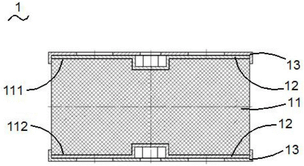
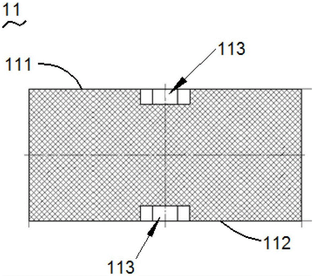
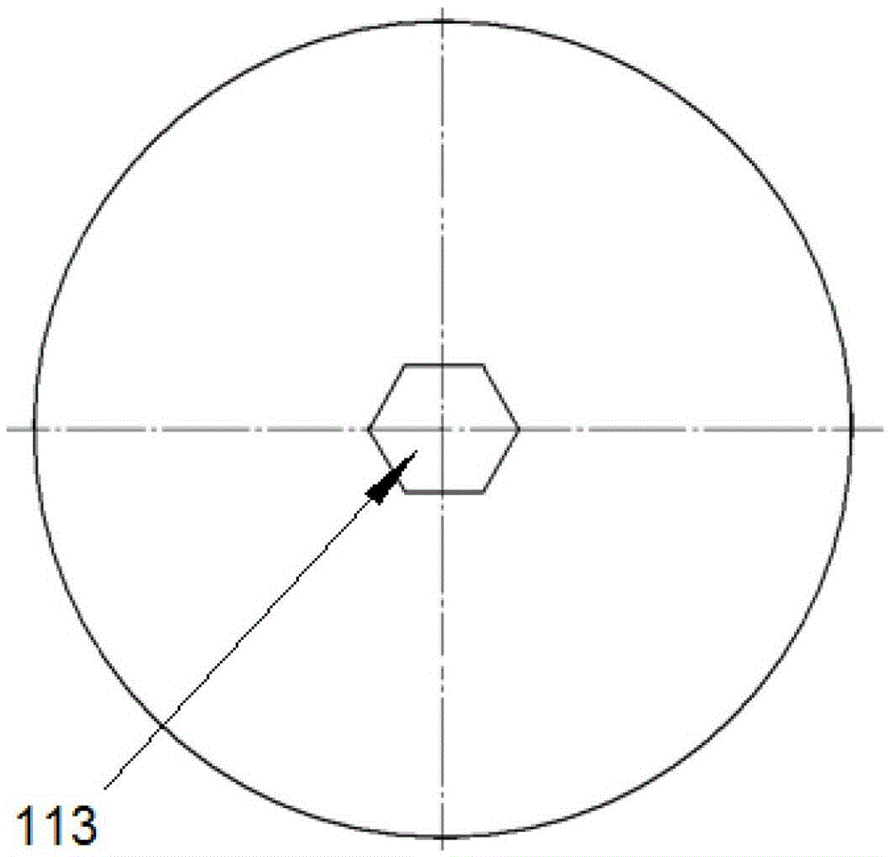
[0023] see figure 1 , figure 1 Shown is the assembly diagram of the automobile engine rubber mount of the present invention. The automobile engine rubber mount 1 includes a rubber part 11, the rubber part 11 has a cylindrical structure, and the middle part of the first cylindrical surface 111 and the middle part of the second cylindrical surface 112 of the rubber part 11 are respectively provided with a corresponding container. A hole 113; a positioning plate 12, the positioning plate 12 is respectively arranged on the first cylindrical surface 111 and the second cylindrical surface 112 of the rubber member 11; and a fixed plate 13, the fixed plate 13 is respectively arranged on the corresponding The side of the positioning plate 12 is...


PUM


Abstract

Disclosed is a rubber suspension for an automobile engine. The rubber suspension comprises a rubber part, positioning plates and fixing plates. The rubber part is in a cylindrical structure, accommodation holes are formed in the middle of a first cylindrical surface and the middle of a second cylindrical surface of the rubber part respectively and correspondingly, and depths of the accommodation holes are smaller than the cylinder height of the rubber part; the positioning plates are arranged on the first cylindrical surface and the second cylindrical surface of the rubber part respectively and correspondingly; and each fixing plate is correspondingly arranged on one side of each positioning plate, which is opposite to the rubber part. By means of the rubber suspension, uniform deformation is performed on positions of the rubber suspension of the automobile by an automobile frame, the working performance is strengthened, heat generation by friction due to vibration among portions is eliminated, and aging of rubber is prevented. Besides, oil erosion to the rubber suspension is effectively prevented, and the service life of the rubber suspension is prolonged.

Description

technical field [0001] The invention relates to the technical fields of automobile engineering and power engineering, in particular to an automobile engine rubber mount. Background technique [0002] With the development of science and technology and the continuous increase of car ownership, people have higher and higher requirements for the safety and comfort of car passengers. In various fuel engine vehicles, due to engine critical knock combustion expansion and piston linkage movement, vibration and noise are transmitted to the passenger compartment through the chassis and body of the vehicle, causing adverse effects on the vehicle driver and passengers. At present, good ride comfort and low noise are one of the important symbols of advanced automobile technology, and have become the goal of technological competition among developed countries and major automobile manufacturers. Because the fuel engine and internal combustion engine installed on the car provide power to t...

Claims


Application Information

Patent Timeline
Patent Type & Authority Patents(China)
IPC IPC(8): F16F1/371
Inventor 邹海荣田玉冬
Owner SHANGHAI DIANJI UNIV
Why Eureka
Eureka Blog
Learn More