Unmanned aerial vehicle low impact catapult pneumatic and hydraulic system
What is Al technical title?
Al technical title is built by PatSnap Al team. It summarizes the technical point description of the patent document.
A kind of ejection device, pneumatic hydraulic technology, applied in the direction of launch/drag transmission device, fluid pressure actuation device, mechanical equipment, etc., can solve the problems of difficult processing, large impact at the start-up stage, complex process, etc., and achieve high reliability and low impact Ejection, overcoming the effect of large impact
Inactive Publication Date: 2015-06-10
YANSHAN UNIV
View PDF6 Cites 0 Cited by
Summary
Abstract
Description
Claims
Application Information
AI Technical Summary
This helps you quickly interpret patents by identifying the three key elements:
Problems solved by technology
Method used
Benefits of technology
Problems solved by technology
[0004] However, the traditional UAV pneumatic-hydraulic ejection technology still has shortcomings. Firstly, the impact at the start-up stage is large, and it is difficult to realize stepless speed regulation; secondly, high-speed hydraulic cylinders are often used in the acceleration process, which is difficult to process and complicated.
Method used
Image
Click on the blue label to locate the original text in one second.
Reading with bidirectional positioning of images and text.
Examples
Embodiment Construction
[0020] Below in conjunction with accompanying drawing and specific embodiment the present invention is described in further detail:
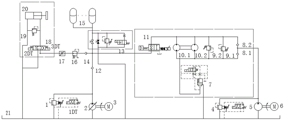
[0021] A gas-hydraulic system of a UAV low-impact ejection device, such as figure 1 As shown, it is composed of main oil pump electromagnetic unloading overflow valve 1, main oil pump 2, main oil pump motor 3, charging pump electromagnetic unloading overflow valve 4, charging pump 5, charging pump motor 6, cartridge valve 7, second A one-way valve 8 and its safety valve 9, hydraulic motor 10, electro-hydraulic proportional cartridge valve 11, second one-way valve 12, safety and shut-off valve block 13, third one-way valve 14, accumulator 15, reducing Pressure valve 16, speed control valve 17, electromagnetic reversing valve 18, proportional overflow valve 19, deceleration hydraulic cylinder 20, oil tank 21 and oil pipes connected between each original; the main oil pump motor 3 drives the main oil pump 2, the main oil pump 2. The oil suction po...
PUM
Abstract
The invention relates to an unmanned aerial vehicle low impact catapult pneumatic and hydraulic system which is composed of a main oil pump electromagnetic unloading overflow valve, a main oil pump, a main oil pump motor, a supplemented oil pump electromagnetic unloading overflow valve, a supplemented oil pump, a supplemented oil pump motor, a cartridge valve, a first one-way valve, a safety valve, a motor, an electric-hydraulic proportional cartridge valve, a second one-way valve, a safety and stop valve, a third one-way valve, an energy accumulator, a pressure reducing valve, a speed regulating valve, an electromagnetic change valve, a proportional overflow valve, a decelerating hydraulic cylinder, an oil tank and oil pipes communicated with each element. According to the unmanned aerial vehicle low impact catapult pneumatic and hydraulic system, the hydraulic motor is adopted so as to drive a winding drum mechanism, the shortages that a high-speed hydraulic cylinder is adopted by a traditional pneumatic and hydraulic system and thus technology is complex and machining difficulty is large are overcome; the hydraulic motor is controlled by a proportional valve and closed-loop control is conducted on the rotation speed of the hydraulic motor, so that the ejection with high reliability and low impact in a start stage is achieved, and the shortages that the traditional pneumatic and hydraulic system is large in impact and poor in reliability are overcome.
Description
technical field [0001] The invention relates to a UAV ejection device, in particular to a gas-hydraulic system of a UAV low-impact ejection device. Background technique [0002] The ejection mechanism is widely used in the military field, such as the launch of missiles and rockets, the launch of carrier-based aircraft, the ejection of drones, the ejection of lifesaving seats, and the ejection and launch of satellites from space stations, space shuttles or other aircraft. [0003] There are many ways to launch UAVs, such as hand throwing, airborne delivery, vehicle launch, ejection, rocket boosting, etc. Commonly used UAV ejection methods include elastic ejection, gas ejection, electromagnetic ejection and gas-hydraulic ejection. Elastic ejection uses the elastic force of elastic elements (such as rubber bands and springs) with strong stretchability as power to provide the acceleration required for take-off, which is suitable for light (small) drones; gas ejection refers to ...
Claims
Application Information
Patent Timeline
Application Date:The date an application was filed.
Publication Date:The date a patent or application was officially published.
First Publication Date:The earliest publication date of a patent with the same application number.
Issue Date:Publication date of the patent grant document.
PCT Entry Date:The Entry date of PCT National Phase.
Estimated Expiry Date:The statutory expiry date of a patent right according to the Patent Law, and it is the longest term of protection that the patent right can achieve without the termination of the patent right due to other reasons(Term extension factor has been taken into account ).
Invalid Date:Actual expiry date is based on effective date or publication date of legal transaction data of invalid patent.