
Cross-flow fan for air conditioning that can effectively improve fan performance

A technology of cross-flow fans and fans, which is applied to components of pumping devices for elastic fluids, non-variable-capacity pumps, machines/engines, etc. To achieve the effect of simple structure, noise reduction, and fan noise reduction

Active Publication Date: 2016-05-04
GUANGDONG SUNWILL PRECISING PLASITC CO LTD
View PDF6 Cites 0 Cited by
  • Summary
  • Abstract
  • Description
  • Claims
  • Application Information

AI Technical Summary

Problems solved by technology

The shape of the blade-shaped both ends of the existing common cross-flow fan blade is basically the same, as Figure 4 As shown, the disadvantage of this type of cross-flow fan is that there is a strong eccentric vortex inside the fan during operation, and the fluid near the volute tongue in the volute area recoils back to the inside of the impeller, and this part of the airflow does work on the impeller, but The airflow angle of this part of the air inlet is quite different from the blade inlet angle, and it is easy to form a large low-speed area and a vortex area on the pressure surface of the blade.
Due to the strong interaction between the low-speed area and the eccentric vortex area, the eccentric vortex is pulled to move to the impeller inlet, which is not conducive to the increase of air volume, and it will generate a lot of noise, which is difficult to meet the requirements of consumers.

Method used


Image

  • Cross-flow fan for air conditioning that can effectively improve fan performance
  • Cross-flow fan for air conditioning that can effectively improve fan performance
  • Cross-flow fan for air conditioning that can effectively improve fan performance

Examples


Embodiment Construction

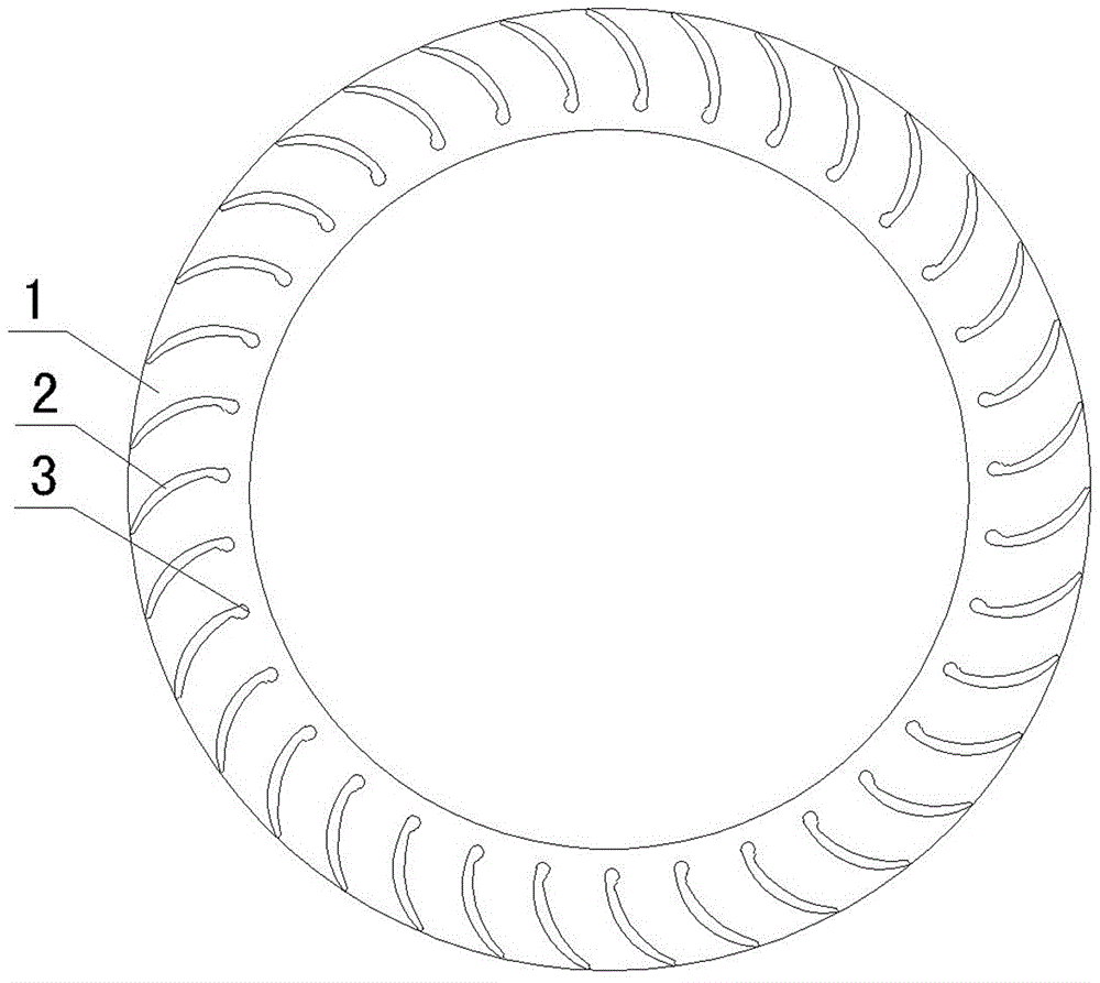
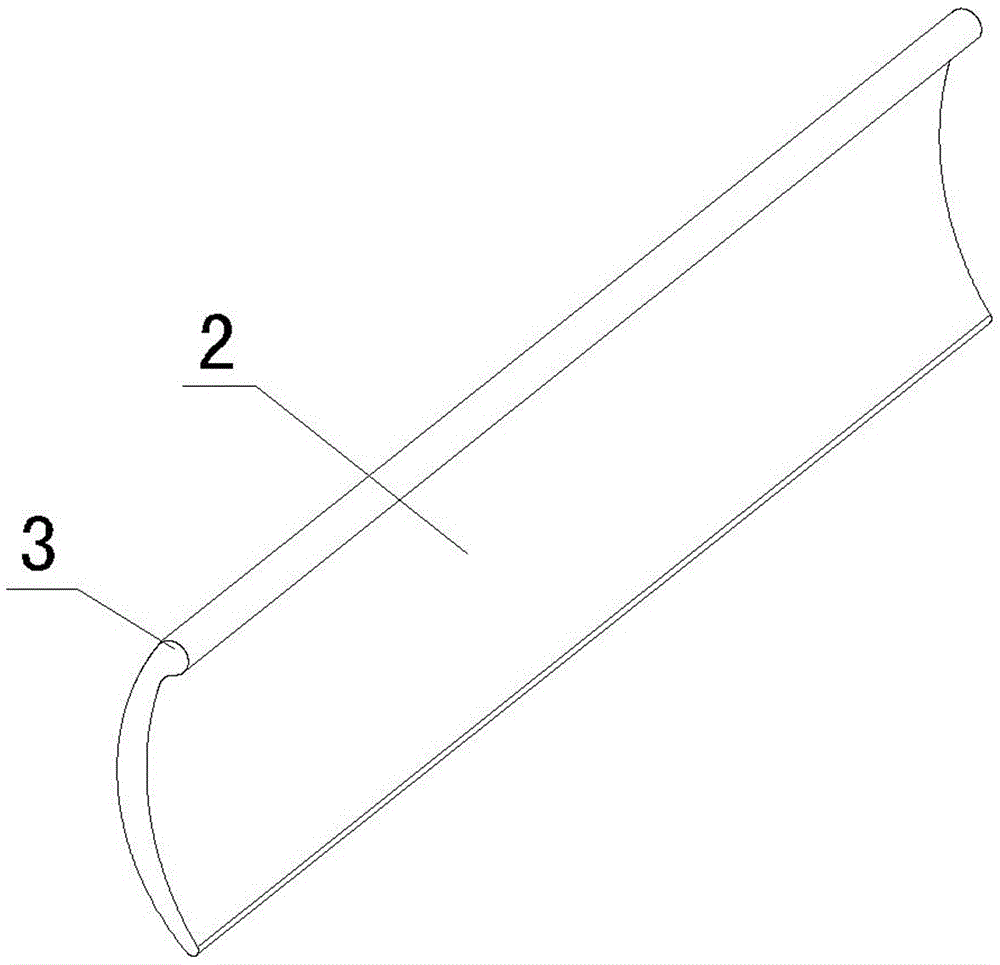
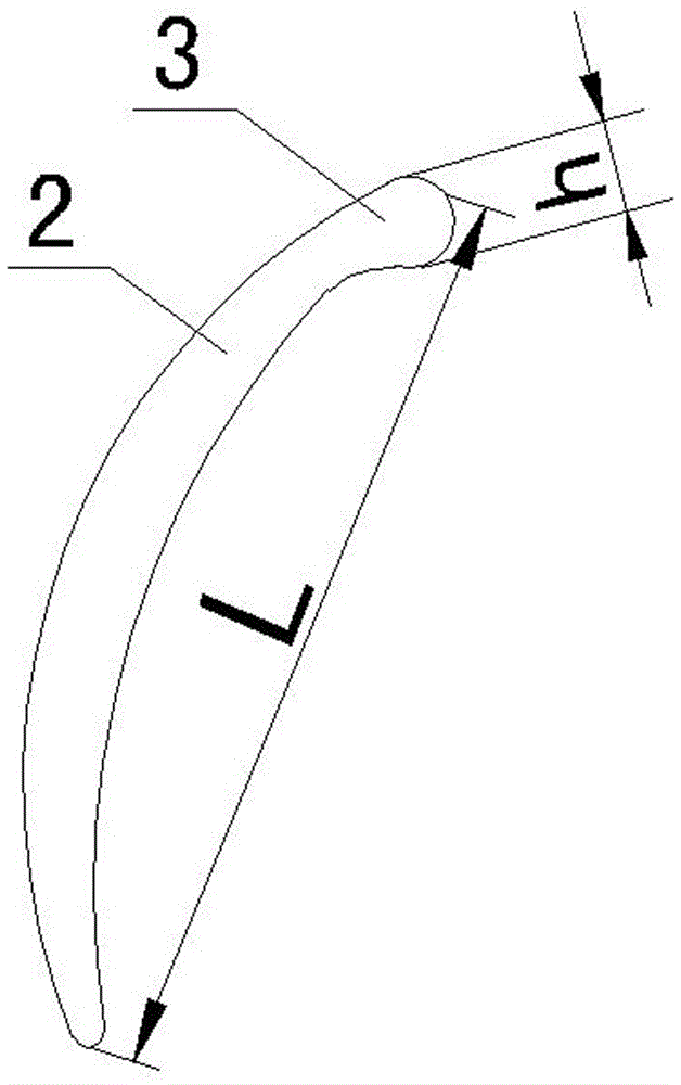
[0020] Such as Figure 1-Figure 3 As shown, the air-conditioning cross-flow fan that can effectively improve fan performance in the present invention includes an impeller, a motor, a volute 4, a volute tongue 5, and an evaporator 6, wherein the impeller includes an impeller body 1 and grounds arranged at certain intervals. A plurality of blades 2 installed on the circumference of the impeller body 1, the blades 2 are bent toward the rotation direction of the impeller body 1, in order to effectively improve the performance of the fan of the present invention, the inner end of the blade 2 (also The end of the blade 2 near the inlet of the inner diameter of the impeller) is provided with a disturber structure 3 that can disrupt the interconnection between the eccentric vortex formed inside the impeller and the low-speed wake flow. During the use of the present invention, the kinetic energy recoiled back into the impeller can be fully utilized to improve the performance of the fan...


PUM


Abstract

The invention discloses an air conditioner cross-flow fan capable of effectively improving fan performance. The air conditioner cross-flow fan capable of effectively improving the fan performance comprises an impeller. The impeller comprises an impeller body and a plurality of blades arranged on the circumference of the impeller body in a spaced mode. The blades are bent towards the rotary direction of the impeller body. The air conditioner cross-flow fan capable of effectively improving the fan performance is characterized in that a perturbator structure capable of disordering the mutual connection of an eccentric vortex inside the fan and low-speed tail airflow is arranged at the inner side ends of the blades, so that when the air conditioner cross-flow fan capable of effectively improving the fan performance is used, the zone of the eccentric vortex inside the impeller is reduced and a low-speed zone formed by the eccentric vortex and the tail of the impeller is reduced through the action of the perturbator structure. Further, a high-speed jet zone with the speed obviously higher than that of a traditional blade type cross-flow fan is generated in an outlet zone by the impeller of the cross-flow fan. A high-speed jet disorders the mutual connection of the eccentric vortex and the low-speed tail airflow and has the function of a perturbator, so that blocking of a low-speed zone inside the impeller is reduced, the air volume of the fan is improved, and the noise of the fan is reduced.

Description

technical field [0001] The invention relates to the field of air conditioners, in particular to a cross-flow fan which is suitable for on-hook air conditioners and can effectively improve the performance of the fan. Background technique [0002] The cross-flow fan is driven by the cross-flow fan impeller to exchange heat with the heat exchanger. The larger the air volume, the more obvious the heat exchange effect, so it is widely used in the hanger in the field of air conditioning. Existing cross-flow fans include an impeller part, a motor, a volute, a volute tongue and an evaporator, wherein the impeller part includes an impeller body and a plurality of blades arranged at certain intervals on the circumference of the impeller body, and the The blades are bent toward the direction of rotation of the impeller body. Its working principle is: the motor drives the part of the impeller to rotate, forming a vortex inside the part of the impeller, and forcing air convection (that...

Claims


Application Information

Patent Timeline
Patent Type & Authority Patents(China)
IPC IPC(8): F04D29/26F04D29/66
Inventor 毛军祥杨昕温选峰周凯
Owner GUANGDONG SUNWILL PRECISING PLASITC CO LTD
Learn More