
A wave energy pump

A wave energy, one-to-one technology, applied in the direction of pumps, piston pumps, ocean energy power generation, etc., can solve the problems of not considering the unfavorable factors of torsional force, working reliability and wave energy absorption efficiency limitations, etc., to reduce working friction, The effect of improving collection efficiency

Inactive Publication Date: 2015-09-30
TSINGHUA UNIV
View PDF8 Cites 1 Cited by
  • Summary
  • Abstract
  • Description
  • Claims
  • Application Information

AI Technical Summary

Problems solved by technology

However, since the device does not consider the unfavorable factors of torsional force existing between each cylindrical floating body, and the wave energy harvesting floating body is limited to a cylindrical floating body structure, its working reliability and wave energy absorption efficiency are limited

Method used


Image

  • A wave energy pump
  • A wave energy pump
  • A wave energy pump

Examples


Embodiment 1

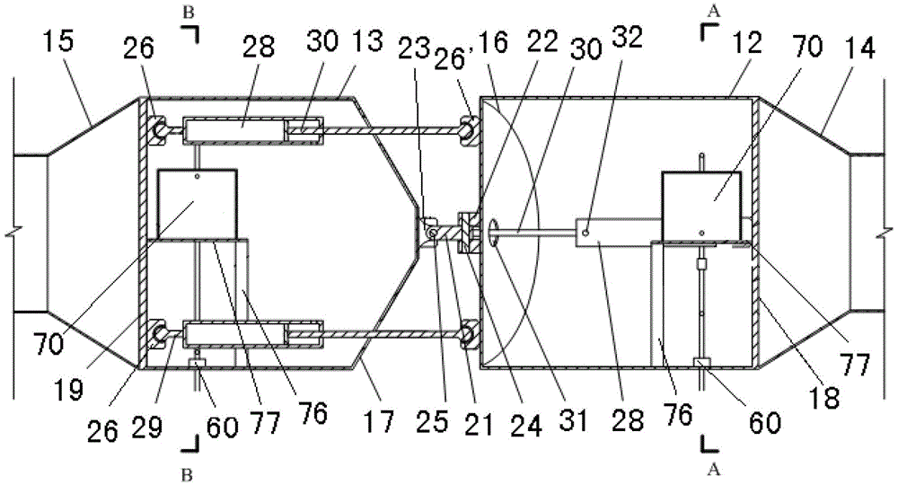
[0032] like figure 1 , image 3 , Figure 4 As shown, each connecting member 20 in this embodiment includes a connecting rod 21, and the two ends of the connecting rod 21 respectively have a single earring, and the axes of the ring holes of the two single earrings are perpendicular to each other. Correspondingly, a pair of earrings 22, 23 are arranged at the center of the end faces of the front and rear end sections 12, 13 of the adjacent two floating bodies 10, respectively. Coinciding with the symmetry planes of a pair of wedge surfaces at the corresponding end, the two single clevises of the connecting rod 21 are rotatably connected to the two pairs of clevises 22 , 23 of the floating body 10 at both ends through two pin shafts 24 , 25 . As can be seen from the accompanying drawings, when the adjacent two floating bodies 10 swing up and down relative to the pin shaft 25 (as image 3 shown), the pair of wedge surfaces 17 provided at the end of the rear end section 13 of t...

Embodiment 2

[0035] like figure 2 , Figure 5 , Figure 6 As shown, the difference between this embodiment and Embodiment 1 is that in the connecting member 20 of this embodiment, instead of setting a connecting rod 21, two identical turntables 33 are set between two adjacent floating bodies 10 , 34, a set of turntable bearings 35 connecting the two into one body is set between the two turntables 33, 34, so that the two turntables 33, 34 can rotate relatively. A pair of single earrings 36,37 are respectively symmetrically arranged on the outer disk surfaces of two adjacent floating bodies 10 of two rotating disks 33,34, and the symmetrical planes of the two single earrings 36 on the left rotating disk 33 are the same as the two single earrings 37 on the right rotating disk 34. The planes of symmetry are perpendicular to each other. Corresponding to the two pairs of single clevis 36, 37, a pair of double clevis 38 is arranged at the end of the rear end section 13 of the floating body 10...


PUM


Abstract

The invention relates to a wave energy pump. The wave energy pump is characterized by comprising a plurality of wave energy collecting floating bodies, a plurality of connecting components used for connecting every two adjacent floating bodies, an anchoring device which is connected at the front end of a first floating body, a plurality of sea water pre-processing devices arranged in the floating bodies, and a high-pressure sea water post-processing device. A single-lug ring and a double-lug ring which are opposite to each two floating bodies are arranged on each connecting component and are connected through a pin shaft, and accordingly the adjacent floating bodies can freely swing in an up-and-down and left-to-right mode. A hydraulic cylinder and a piston rod are connected in each floating body through a ball hinged support, and wave energy is directly and efficiently converted into hydraulic energy by the full utilization of relative movement between every two adjacent floating bodies. The wave energy pump is convenient to assemble and disassemble, when sea circulations with bad wave conditions such as typhoon happen or when the wave energy pump needs to be examined and repaired, floating bodies and the first floating body can be disconnected on the water surface, and the wave energy collecting floating bodies are dragged and transported to a safe sea area to avoid risks or to be examined and repaired. The wave energy pump supplies efficient hydraulic power for sea water desalination, power generation and the like, and can be widely applied to the process of developing sea energy.

Description

technical field [0001] The invention relates to a liquid pump, in particular to a wave energy pump which utilizes ocean wave energy to drive a piston. Background technique [0002] With the depletion of non-renewable energy sources such as fossils, countries around the world have gradually turned their attention to the ocean. Especially in the 1970s, the upsurge in the development of ocean energy gradually started. In the 21st century, the international community's attention to ocean energy has risen sharply. As a renewable clean energy, wave energy has a high energy flow density and is the highest grade and most widely distributed energy in ocean energy. It is a long-term wish of people to convert the inexhaustible wave energy into useful energy. However, due to the instability of wave energy, it brings difficulties to the practical application of wave energy. The key technology of wave energy utilization is the wave energy conversion device. Usually, the wave energy need...

Claims


Application Information

Patent Timeline
Patent Type & Authority Patents(China)
IPC IPC(8): F04B35/02F03B13/16
CPCY02E10/38Y02A20/144Y02E10/30
Inventor 张永良郑思明
Owner TSINGHUA UNIV
Learn More