
Photoelectric direct-current micro-grid power source device and control method

A DC micro-grid and power supply device technology, applied in the direction of DC network circuit devices, circuit devices, electrical components, etc., can solve the problems of difficult to maintain stable output bus voltage, complex structure, long recovery period, etc., to achieve good versatility and use. Value, reduce environmental pollution, reduce the effect of cost of use

Inactive Publication Date: 2013-08-28
JIASHAN MINGSHI ELECTRIC POWER SCI & TECH
View PDF3 Cites 16 Cited by
  • Summary
  • Abstract
  • Description
  • Claims
  • Application Information

AI Technical Summary

Problems solved by technology

[0003] At present, photovoltaic and grid complementary power generation devices mostly use the energy emitted by photovoltaic panels as the main energy, and the grid as auxiliary energy. Due to the intermittent nature of photovoltaic energy, it is difficult to maintain the stability of the output bus voltage.
Other forms of DC micro-grid power supply often need to add additional equipment such as batteries to maintain a stable power supply at the output end. The structure is complex, the cost is high, and the recovery period is long.
Especially in the civil market of small and medium power levels with broad market potential, high cost has become synonymous with photovoltaics, which seriously hinders the development of the photovoltaic market

Method used

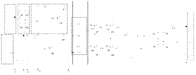

Image

  • Photoelectric direct-current micro-grid power source device and control method
  • Photoelectric direct-current micro-grid power source device and control method
  • Photoelectric direct-current micro-grid power source device and control method

Examples


Embodiment Construction

[0021] In order to make the present invention more comprehensible, a preferred embodiment is described in detail below with accompanying drawings.

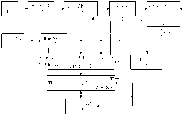
[0022] The purpose of the present invention is to design a photoelectric DC micro-grid power supply device and control method with simple structure, low cost and strong versatility, aiming at the characteristics of distributed photovoltaic DC micro-grid power supply. The structure of the device is as figure 1 As shown, it includes a full-bridge rectifier. The input end of the full-bridge rectifier is connected to the power grid, and the output end realizes the synchronization of the input current and the grid voltage and the stability of the DC bus voltage through the power factor correction unit. The input end of the Boost converter is connected to both ends of the photovoltaic panel, and the output end is connected to the DC bus capacitor bank. The DC bus voltage realizes the step-up or step-down of the output DC voltage throug...


PUM


Abstract

The invention relates to a direct-current bus photoelectric real-time confluence system and a control method, and belongs to the field of distributed photovoltaic direct-current micro-grid power sources. The direct-current bus photoelectric real-time confluence system comprises a direct-current input source which is connected with a one-way rectification controller, and the output end of the one-way rectification controller is connected with a bus capacitor bank. The input end of the bus capacitor bank is connected with a DC / DC converter which is used for achieving adjustment of output power of a photovoltaic cell panel. Two ends of the bus capacitor bank are connected with a discharging circuit in parallel, and meanwhile the output end of the bus capacitor bank is connected with a direct-current load. By means of multilevel hysteresis control of the voltage of the bus capacitor bank, the working mode of the system is confirmed, therefore, direct-current stabilized-voltage output is achieved, and normal power supply of the load is guaranteed. On the premise that stabilization of the output voltage is guaranteed, the photovoltaic cell panel is used as auxiliary energy, real-time confluence of photovoltaic energy and the direct-current input source is achieved, the energy utilization rate is improved, power generation cost is lowered, environmental pollution is reduced, and good universality and practical value are obtained.

Description

technical field [0001] The invention relates to a photoelectric DC micro-grid power supply device and a control method. The invention belongs to the field of distributed photovoltaic DC micro-grid power supply, and in particular relates to a photoelectric DC micro-grid power supply device and a control method. Background technique [0002] The photoelectric DC micro-grid power supply device and control method belong to the category of micro-grid power supply, and ensuring stable output voltage is an important technical index of the micro-grid power supply. The use of photovoltaic and grid complementary power generation is an important branch of distributed power generation technology. [0003] At present, photovoltaic and grid complementary power generation devices mostly use the energy emitted by photovoltaic panels as the main energy, and the grid as auxiliary energy. Due to the intermittent nature of photovoltaic energy, it is difficult to maintain the stability of the o...

Claims


Application Information

Patent Timeline
Patent Type & Authority Applications(China)
IPC IPC(8): H02J1/00
Inventor 吴乐彬彭乐乐王玉玲沈一华潘月辉
Owner JIASHAN MINGSHI ELECTRIC POWER SCI & TECH
Learn More