Rotating mechanism of trailer tail frame
A technology of a rotating mechanism and a tailstock, which is applied in the directions of motor vehicles, substructures, vehicle parts, etc., can solve the problems of not being able to turn upwards, and cannot be satisfied at the same time, and achieve the effect of smooth turning
- Summary
- Abstract
- Description
- Claims
- Application Information
AI Technical Summary
Problems solved by technology
Method used
Image
Examples
Embodiment 1
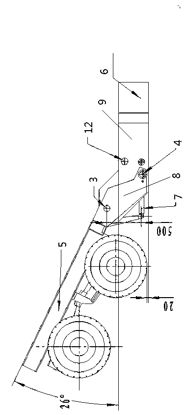
[0040] As a preferred embodiment of the present invention, it includes a chassis tailstock 5 and a chassis seat frame 6, on which the chassis tailstock 5 is fixedly mounted with an overturn support 8, and the chassis tailstock 5 is hinged to the chassis seat frame 6 through the overturn support 8 , the chassis tailstock 5 rotates around the hinge center to make the chassis tailstock 5 turn up and down, refer to the attached manual figure 1 , that is, a schematic diagram of the structure of the inverted state of the present invention is given. When the chassis tailstock 5 is turned up, the height between the chassis seat frame 6 and the ground can be reduced, so that the large-scale The device 15 is also lowered in height.
Embodiment 2
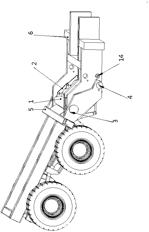
[0042] As yet another preferred embodiment of the present invention, the overturning support 8 is provided with an overturning support shaft 3, and the support base 9 is fixedly installed on the chassis seat frame 6, and the overturning support shaft 3 runs through the overturning support 8 and the support base 9, The chassis tailstock 5 is hinged with the chassis seat frame 6 through the turning support shaft 3. When the goods are loaded on the chassis seat frame 6, the chassis tailstock 5 turns upwards. At this time, the turning support 8 also turns over together, and the support Seat 9 then does not overturn, and support seat 9 moves downward gradually along with chassis seat frame 6. Such a structural form makes the turning over of the chassis tailstock 5 more gentle, and the rest are the same as in Embodiment 1.
Embodiment 3
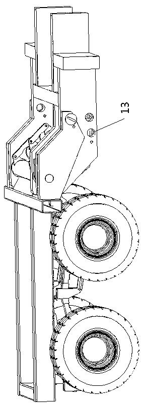
[0044] Refer to the attached image 3, as another preferred embodiment of the present invention, a spring torsion accumulator 1 is installed between the support bases 9, the spring torsion accumulator 1 includes a pin shaft, a torsion spring 10 sleeved on the pin shaft and a torsion spring sleeved on the torsion The outer tube 11 outside the spring 10, the two ends of the pin shaft are fixed on the support seat 9, one end of the torsion spring 10 is fixed on the pin shaft, and the other end of the torsion spring 10 is fixed on the outer tube 11, under the action of the torsion spring 10 The outer tube 11 is driven to rotate, and the outer tube 11 is connected with the chassis tailstock. There are three spring torsion accumulators 1 , and the outer tubes 11 of every two spring torsion accumulators 1 are connected and driven by a link mechanism 2 . The turning support 8 and the support seat 9 are respectively provided with a marching state locking pin hole 12 and a turned over ...
PUM
 Abstract
Description
Claims
Application Information
 - R&D
- Intellectual Property
- Life Sciences
- Materials
- Tech Scout
- Unparalleled Data Quality
- Higher Quality Content
- 60% Fewer Hallucinations
Browse by: Latest US Patents, China's latest patents, Technical Efficacy Thesaurus, Application Domain, Technology Topic, Popular Technical Reports.
© 2025 PatSnap. All rights reserved.Legal|Privacy policy|Modern Slavery Act Transparency Statement|Sitemap|About US| Contact US: help@patsnap.com


