


Quick Research
Generate reliable direction feasibility study reports for your R&D in just a few steps.

Technical Q&A
Discover and master advanced knowledge NOW. Basics, ideas, possibilities, all at once.

Find Solutions
As an expert in R&D theories, this can generate solutions to your technical problems instantly.

Evaluate Feasibility
Analyze your overall solution with one click, know your potential R&D risks in advance.

Monitor Landscape
Get weekly tech updates, stay abreast of the latest tech innovations and key insights.
Multi-section bending radius numerical-control die-free bending shaping method and equipment
A technology of bending radius and forming equipment, which is applied in the direction of heat exchange equipment, etc., can solve the problem that the arc processing of multiple sections with different bending radii is difficult to realize, and achieve the effect of avoiding overturning and avoiding wear
- Summary
- Abstract
- Description
- Claims
- Application Information
AI Technical Summary
Problems solved by technology
Method used
Image

Examples
Embodiment 1
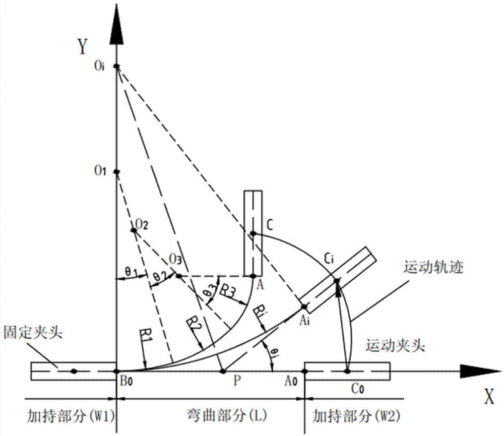
[0042] Such as figure 1 As shown, the principle diagram of the method of the present invention is shown in the figure: the workpiece is divided into three parts: the holding part W1, the bending part L, and the holding part W2. The holding part W1 is clamped with a fixed chuck, and the holding part W2 is clamped with a moving chuck. The bending part L is from the end B0 of the fixed chuck to the head end A0 of the moving chuck. Point C is the midpoint of the moving chuck after bending. The center of the moving chuck moves from C0 to Ci, and then to point C. The radius of curvature Ri is the radius of curvature when the bending angle is θi. figure 1 The middle O1, O2, and O3 are the centers of the circle when the radius of curvature is R1, R2, and R3, respectively. figure 1 The middle O1, O2, and O3 are the centers of the circle when the radius of curvature is R1, R2, and R3, respectively. Therefore, as long as you know the start and end positions of the workpiece, and the radi...
Embodiment 2
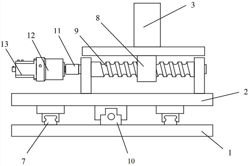
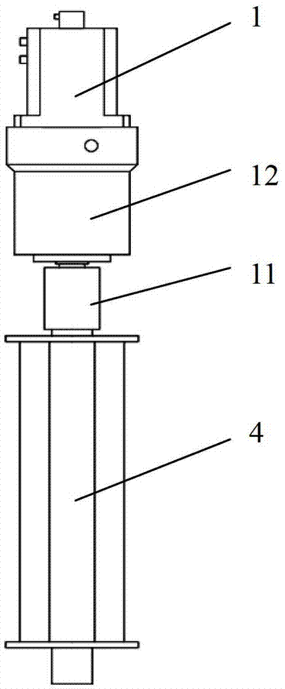
[0063] This embodiment provides a dieless bending forming equipment, which includes a translational chuck and a rotating chuck, a driving device, a bending platform, and a numerical control system. Such as Figure 2-3 As shown in the figure: 1: base, 2: sliding platform, 3: translational chuck, 4: rotating chuck, 7: guide rail, 8: screw connection block, 9: screw, 10: screw support seat , 11: coupling, 12: reducer, 13: servo motor. Among them: the base 1, the sliding platform 2, and the guide rail 7 constitute the bending platform; the screw connecting block 8, the screw 9, the screw support 10, the coupling 11, the reducer 12, and the servo motor 13 constitute the driving device.
[0064] The guide rail 7 is arranged on the base 1 and the sliding platform 2. The guide rail on the bottom plate 1 and the guide rail on the sliding platform are perpendicular to each other, and the translational chuck 3 is connected with the screw 9 on the sliding platform 2 through the screw connec...
Embodiment 3
[0068] In another embodiment of the present invention, the moldless bending forming equipment used is such as Figure 4 As shown, the difference from Embodiment 2 lies in: two rails parallel to the Y-direction are installed on the base 1 to support and guide the Y-direction linear movement of the sliding platform 2, and two parallel to the front are installed on the sliding platform 2. The guide rail is used to support and guide the linear movement of the translational chuck in the X direction. There is a sprocket with a small modulus in the reduction box 6, and the large sprocket under the chuck 4 is driven by the chain to rotate the chuck 4.
[0069] Such as Figure 5 As shown, the working steps of the equipment are: pass the workpiece through the translational chuck 3, then clamp the workpiece, and then pass through the rotating chuck 4, control the speed of the servo motor according to the numerical control program, and then control the ball screw and rotation The precise rota...
PUM
| Property | Measurement | Unit |
|---|---|---|
| torque | aaaaa | aaaaa |
| torque | aaaaa | aaaaa |
Abstract
Description
Claims
Application Information
 - R&D Engineer
- R&D Manager
- IP Professional
- Industry Leading Data Capabilities
- Powerful AI technology
- Patent DNA Extraction
Browse by: Latest US Patents, China's latest patents, Technical Efficacy Thesaurus, Application Domain, Technology Topic, Popular Technical Reports.
© 2024 PatSnap. All rights reserved.Legal|Privacy policy|Modern Slavery Act Transparency Statement|Sitemap|About US| Contact US: help@patsnap.com