
Hydraulic barrel shaper

A shaper and hydraulic technology, applied in the field of hydraulic shapers, can solve the problem of insignificant shaping effect, and achieve the effect of simple and convenient operation and high shaping precision.

Active Publication Date: 2013-08-28
JIANGSU PACIFIC HYDRAULIC MACHINERY MFGCO
View PDF4 Cites 10 Cited by
  • Summary
  • Abstract
  • Description
  • Claims
  • Application Information

AI Technical Summary

Problems solved by technology

[0002] The current cylinders, especially the large-diameter cylinders, do not have special mechanical equipment, and there are many inconveniences. At the same time, the plastic effect is not obvious.

Method used


Image

  • Hydraulic barrel shaper
  • Hydraulic barrel shaper
  • Hydraulic barrel shaper

Examples


Embodiment Construction

[0017] The present invention will be further described below in combination with specific embodiments.

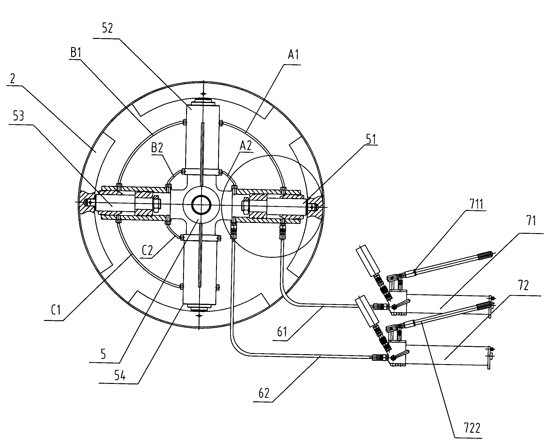
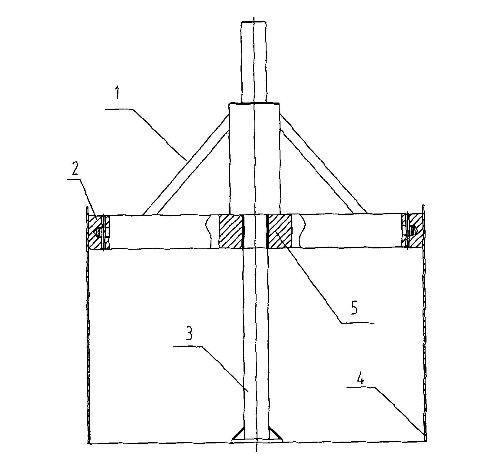
[0018] Such as figure 1 , 2 , 3, and 4, a cylinder hydraulic shaper is composed of a column 3 and a support frame 1, and a combined oil cylinder 5 is fixedly arranged on the column 3, and the combined oil cylinder 5 is composed of a cylinder one 51 and an oil cylinder two 52 1, oil cylinder three 53, oil cylinder four 54 are formed, and the top of the piston rod 9 of described oil cylinder one 51, oil cylinder two 52, oil cylinder three 53, oil cylinder four 54 is all correspondingly connected with shaping block 2.

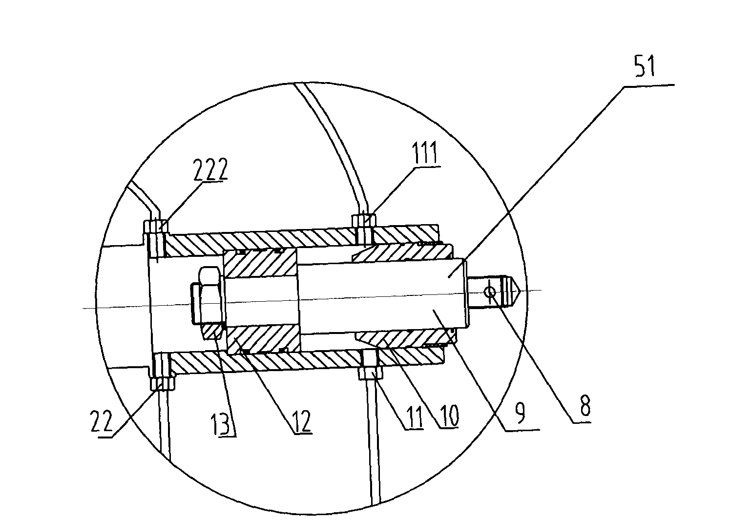
[0019] The oil cylinder 1 51 includes a piston rod 9 , a piston 12 , and a guide sleeve 10 , and the piston 12 is locked by a locking nut 13 .

[0020] The oil cylinder one 51 is provided with an oil inlet pipe joint one 11 and an oil inlet pipe joint two 22, and is correspondingly provided with an oil outlet pipe joint one 111 and an oil outlet pipe joint tw...


PUM


Abstract

A hydraulic barrel shaper comprises an upright column and a support frame. A combined oil cylinder is fixedly arranged on the upright column and comprises a first oil cylinder, a second oil cylinder, a third oil cylinder and a fourth oil cylinder, shaping blocks are correspondingly arranged on tops of piston rods of the first oil cylinder, the second oil cylinder, the third oil cylinder and the fourth oil cylinder in a connected manner, and the shaping blocks with different sizes can be replaced according to actual application conditions. The hydraulic barrel shaper has the advantages that the shaping blocks can be expanded by the aid of high-pressure oil pumps, so that a barrel can be effectively shaped, and the hydraulic barrel shaper can be operated easily and conveniently and is high in shaping precision.

Description

technical field [0001] The invention belongs to the field of hydraulic shapers, in particular to a cylinder hydraulic shaper. Background technique [0002] The current cylinders, especially the large-diameter cylinders, do not have special mechanical equipment when they are in progress, so there are many inconveniences, and the shaping effect is not obvious. Contents of the invention [0003] The object of the present invention is to provide a cylinder hydraulic shaper with reasonable structure, convenient use and good shaping effect. [0004] The technical solution of the present invention is: a cylindrical hydraulic shaper, which is composed of a column and a support frame, and a combined oil cylinder is fixedly arranged on the column, and the combined oil cylinder is composed of oil cylinder one, oil cylinder two, oil cylinder three, and oil cylinder four , the tops of the piston rods of the first oil cylinder, the second oil cylinder, the third oil cylinder, and the f...

Claims


Application Information

Patent Timeline
Patent Type & Authority Applications(China)
IPC IPC(8): B21D3/14
Inventor 邵剑
Owner JIANGSU PACIFIC HYDRAULIC MACHINERY MFGCO
Learn More