Time measurement circuits, methods and systems
A time measurement and circuit technology, applied in the field of circuits, can solve the problems of low measurement accuracy of the time converter, and achieve the effect of improving the accuracy and solving the low measurement accuracy.
- Summary
- Abstract
- Description
- Claims
- Application Information
AI Technical Summary
Problems solved by technology
Method used
Image
Examples
Embodiment Construction
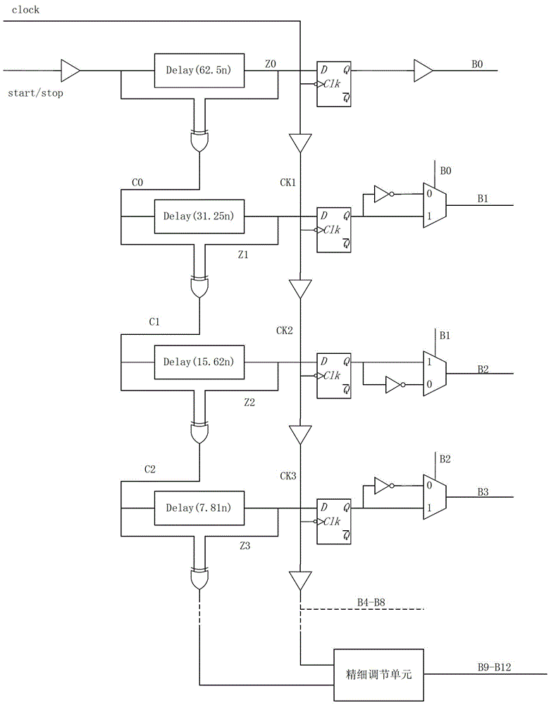
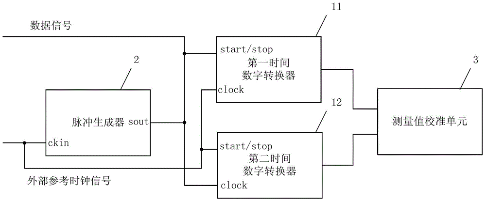
[0036] figure 2 A schematic structural diagram of a time measurement circuit provided by an embodiment of the present invention. like figure 2 As shown, the time measurement circuit can include a time-to-digital converter, a pulse generator 2 and a measurement value calibration unit 3, and the number of time-to-digital converters can be two, which are respectively the first time-to-digital converter 11 and the second time-to-digital converter 11 Converter 12, each time-to-digital converter can convert the input data signal according to the reference clock signal to form a digital code value corresponding to the data signal, and a time-to-digital converter commonly used in the prior art can be used, and its specific structure unlimited, e.g. figure 1 The time-to-digital converter shown.
[0037] Wherein, the clock input terminal (ckin) of the pulse generator 2 is used to receive an external reference clock signal, and generate an internal reference clock signal according t...
PUM
 Abstract
Description
Claims
Application Information
 - R&D
- Intellectual Property
- Life Sciences
- Materials
- Tech Scout
- Unparalleled Data Quality
- Higher Quality Content
- 60% Fewer Hallucinations
Browse by: Latest US Patents, China's latest patents, Technical Efficacy Thesaurus, Application Domain, Technology Topic, Popular Technical Reports.
© 2025 PatSnap. All rights reserved.Legal|Privacy policy|Modern Slavery Act Transparency Statement|Sitemap|About US| Contact US: help@patsnap.com


