Eureka AIR delivers breakthrough ideas for toughest innovation challenges, trusted by R&D personnel around the world.

Device used for fiber laser and capable of filtering out cladding light

A fiber laser, cladding light technology, applied in the direction of cladding fiber, optical waveguide coupling, multi-layer core/cladding fiber, etc., can solve the problems of laser system disaster, inconvenient heat dissipation, fiber burnout, etc. The effect of heat dissipation, reducing heat accumulation, and rapid peeling

Active Publication Date: 2013-08-21
NAT UNIV OF DEFENSE TECH
View PDF4 Cites 21 Cited by
  • Summary
  • Abstract
  • Description
  • Claims
  • Application Information

AI Technical Summary

Problems solved by technology

[0003] At present, there are CN201234052Y (named "Pump and Drain Device for Double-clad Fiber Amplifier and Fiber Laser") and CN101718916A (named "Residual Pumping Device in Stripped Double-clad Fiber") about fiber laser cladding light filtering and cooling schemes. "Method of Light") and other Chinese patent documents have made relevant reports, but these devices only use a high-refractive index light-guiding adhesive layer, and the cladding light will be filtered out in a short length, resulting in local overheating , it is not easy to dissipate heat. When the accumulated heat reaches a certain level, the local part of the optical fiber may be burned due to the high temperature, which will bring disastrous consequences to the entire laser system.

Method used


Image

  • Device used for fiber laser and capable of filtering out cladding light
  • Device used for fiber laser and capable of filtering out cladding light
  • Device used for fiber laser and capable of filtering out cladding light

Examples


Embodiment

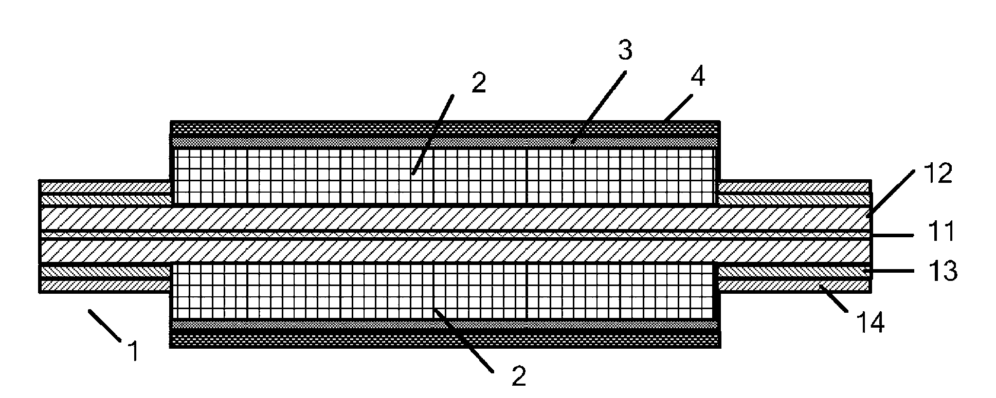
[0025] a kind of like image 3 , 4 The shown device of the present invention for fiber laser and capable of filtering cladding light includes a double-clad energy-transmitting fiber 1, and the double-clad energy-transmitting fiber 1 is a large-mode-field double-clad gain fiber , the length is 2m. Such as figure 2 As shown, the double-clad energy-transmitting optical fiber 1 is composed of a core 11 (mainly composed of silicon dioxide and germanium dioxide), an inner cladding 12, an outer cladding 13, and a coating 14 from the inside to the outside. The middle section of the energy-transmitting optical fiber 1 (can also be multiple sections at intervals in the middle) is a filtering section from which the coating layer 14 and the outer cladding 13 have been stripped, and the length of the filtering section is 10 cm. In the double-clad energy-transmitting optical fiber 1, the diameter of the core 11 is 20 μm, the outer diameter of the inner cladding 12 is 400 μm, the outer c...


PUM

PropertyMeasurementUnit
Lengthaaaaaaaaaa

Abstract

The invention discloses a device used for a fiber laser and capable of filtering out cladding light. The device comprises a double-cladding energy transferring fiber, the double-cladding energy transferring fiber is composed of a fiber core, an inner cladding, an outer cladding and a coating from inside to outside in sequence, one or more sections in the middle of the double-cladding energy transferring fiber are filter-out sections with the coating and the outer cladding removed, at least one core-less fiber with the coating removed is arranged on the periphery of the inner cladding of the filter-out sections in the circumferential direction, the core-less fiber is parallel to the double-cladding energy transferring fiber in the axial direction, a glass sleeve tube is arranged outside the core-less fiber, all of the core-less fiber, the inner cladding of the filter-out sections and the fiber core are covered by the glass sleeve tube, and the outer surface of the glass sleeve tube is coated with a light guiding gel layer. The device used for the fiber laser and capable of filtering out the cladding light is simple in structure, fast and even in heat dissipation, good in safety and capable of effectively filtering out the cladding light in the fiber laser.

Description

technical field [0001] The invention relates to the field of fiber lasers, including fiber oscillators and fiber amplifiers, in particular to a device for fiber lasers and capable of filtering cladding light. Background technique [0002] Fiber laser is a laser that uses optical fiber as the gain medium. By doping different rare earth ions in the fiber matrix material, the laser output of the corresponding band is obtained. In recent years, with the development of high-brightness laser diode pumping technology and large-mode field double-clad doped fiber manufacturing process, the output power of a single double-clad fiber laser has increased rapidly. In 2003, Limpert et al. of Jena University in Germany obtained a 500W continuous laser. In 2004, Jeong et al. of Southampton University in the UK achieved a laser output of 1.36kW. Jeong increased the output power of the laser to 2.1kW by improving the gain fiber parameters and increasing the pump power. In June 2009, the Am...

Claims


Application Information

Patent Timeline
IPC IPC(8): G02B6/24G02B6/255G02B6/245G02B6/036G02F1/01
Inventor 王文亮黄良金冷进勇黄值河孔令超李杰王睿星曹涧秋郭少锋许晓军陈金宝程湘爱姜宗福刘泽金
Owner NAT UNIV OF DEFENSE TECH
Why Eureka
Eureka Blog
Learn More