Temperature detector

A temperature detection device and temperature signal technology, applied in the direction of measuring devices, thermometers, circuit devices, etc., can solve the problems of unbalanced three-phase, inability to protect electrical faults, and inability to detect real-time temperature, so as to prevent electrical fires and prevent electrical fires Effect

Inactive Publication Date: 2013-08-21
WUXI ZIZO ELECTRIC
View PDF0 Cites 6 Cited by
  • Summary
  • Abstract
  • Description
  • Claims
  • Application Information

AI Technical Summary

Problems solved by technology

However, traditional control and protection switch controllers only have basic control functions such as overload long-time delay, short-circuit short-time delay, short-circuit instantaneous, undercurrent, three-phase unbalance, overvoltage and undervoltage protection, etc., and cannot control the main line and electrical equipment. Real-time temperature detection, resulting in fires caused by electrical equipment due to overheating, and cannot fully protect electrical faults

Method used


Image

  • Temperature detector

Examples


Embodiment Construction

[0012] In order to make the purpose, technical solution and advantages of the present invention clearer, the present invention will be further described below in conjunction with the accompanying drawings and embodiments.

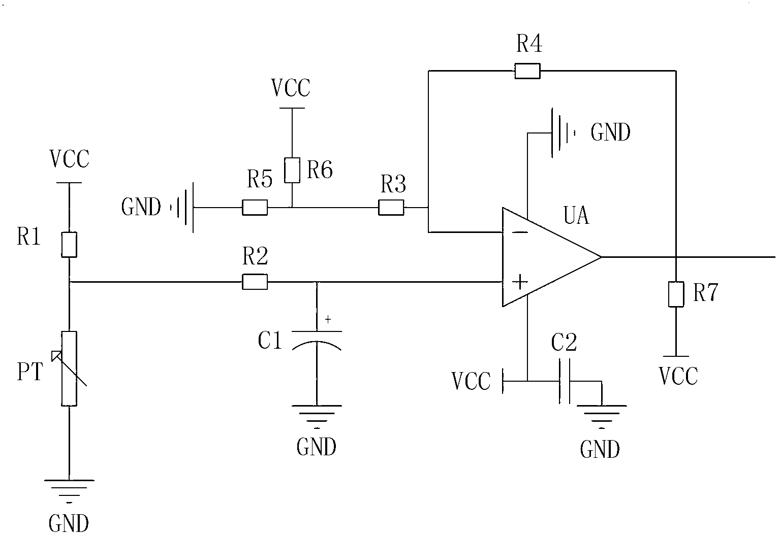
[0013] Please refer to figure 1 As shown, the temperature detection device in this embodiment includes: a temperature signal detection circuit, a temperature signal amplification circuit and a single chip microcomputer (not shown in the figure).

[0014] The temperature signal detection circuit includes a temperature sensor PT, a first resistor R1, a second resistor R2 and a first capacitor C1, and the temperature signal amplifying circuit includes an operational amplifier UA, a third resistor R3, a fourth resistor R4, a fifth resistor R5, the sixth resistor R6, the seventh resistor R7 and the second capacitor C2.

[0015] Wherein, one end of the temperature sensor PT is grounded to GND, the node after the other end is connected to one end of the first res...


PUM


Abstract

The invention discloses a temperature detector. The temperature detector comprises a temperature signal detecting circuit, a temperature signal amplification circuit and a single chip microcomputer. The temperature signal detecting circuit comprises a temperature sensor, a first resistor and a second resistor. The temperature signal amplification circuit comprises an operational amplifier, a third resistor, a fourth resistor, a fifth resistor and a sixth resistor. The sampled temperature value of an electric device is converted to a voltage value through the temperature signal detecting circuit and the voltage value is output to the temperature signal amplification circuit through the temperature signal detecting circuit. The voltage value is amplified through the temperature signal amplification circuit and output to the single chip microcomputer. The input voltage value is processed through the single chip microcomputer, so that the real-time temperature of the electric device is obtained. The temperature of the electric device can be detected in real time, so that the occurrence of electrical fire is prevented and completely eradicated from a source.

Description

technical field [0001] The invention relates to a temperature detection device, in particular to a temperature detection device for controlling and protecting a switch controller. Background technique [0002] The control and protection switch controller has the function of remote automatic control and local manpower control to control and operate, has coordinated and coordinated time-current protection characteristics, and has the function of automatic cooperation between control and protection, and continuous operation after short circuit. It can realize the control and protection of motor load and power distribution load. However, traditional control and protection switch controllers only have basic control functions such as overload long-time delay, short-circuit short-time delay, short-circuit instantaneous, undercurrent, three-phase unbalance, overvoltage and undervoltage protection, etc., and cannot control the main line and electrical equipment. The real-time temper...

Claims


Application Information

Patent Timeline
Patent Type & Authority Applications(China)
IPC IPC(8): G01K7/18G01K1/02H02H5/04
Inventor 陈重王建忠戈浩
Owner WUXI ZIZO ELECTRIC
Why Eureka
Try Eureka