
Band-pass filter with zero reference point for extracting cuff pulse waves and filtering method

A technology of band-pass filter and high-pass filter, applied in the direction of cardiac catheterization, etc., can solve the problems of unable to form the correct pulse wave envelope, uncertain bias voltage, and unequal filter band-pass frequency window

Inactive Publication Date: 2013-08-21
瞿浩正
View PDF0 Cites 4 Cited by
  • Summary
  • Abstract
  • Description
  • Claims
  • Application Information

AI Technical Summary

Problems solved by technology

At present, the methods or circuits proposed in some literatures are incomplete, which leads to the incomplete matching of the bandpass frequency window of the filter with the pulse wave spectrum range, so that the signal output by the filter contains too much noise and cannot form a correct pulse wave envelope. ;Although the passband of the filter is suitable in some documents, a DC bias current is introduced at the non-inverting input terminal of the operational amplifier through a resistor divider at the input terminal. Bias voltage, the pulse wave oscillates around this bias voltage. At this time, when sampling and processing the pulse wave, the bias voltage is the threshold and reference point for observing the pulse wave amplitude
The determinism of the bias voltage depends on the determinism of the voltage dividing resistor set at the input terminal. Since there is always an error between the actual resistance value and the nominal value of the resistor, it will lead to the same design of the filter on different PCBs. The output bias voltage is uncertain, which brings errors to the sampled data processing

Method used


Image

  • Band-pass filter with zero reference point for extracting cuff pulse waves and filtering method
  • Band-pass filter with zero reference point for extracting cuff pulse waves and filtering method
  • Band-pass filter with zero reference point for extracting cuff pulse waves and filtering method

Examples


Embodiment Construction

[0040] Two kinds of tool software that the design filter of the present invention uses are: PROTEL99SE, is the software of a circuit schematic diagram and PCB design, uses this software to draw the circuit schematic diagram and PCB diagram including the filter; MATLAB 7.0, is a The software for scientific calculation is used to complete the calculation tasks involved in the design of the filter of the present invention.

[0041] The schematic diagram of the band-pass filter designed by the present invention is Figure 8 , find the transfer function and transfer curve of the first-stage filter and the second-stage filter respectively.

[0042] Let R5=R3=700K, C8=C17=2.2uf, R5C8=1.54, substitute into the transfer function formula H1(S) of the first-stage filter, and get:

[0043] H1(s) = 2.3716S 2 / (1+3.508S+2.3716S 2 )

[0044] Using MATLAB 7.0 to calculate the curve of the transfer function changing with frequency, the command line is as follows:

[0045] f=0:0.1:1000;

...


PUM


Abstract

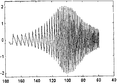
The invention relates to a band-pass filter with a zero reference point for extracting cuff pulse waves and a filtering method, relates to the technical field of electronic sphygmomanometers based on oscillography, and provides a method for extracting weak pulse waves from output signals of a cuff pressure sensor. The band-pass filter is designed and achieved, a band-pass frequency range of the band-pass filter is 0.2Hz-5.0Hz, the frequency spectrum of the pulse waves is matched, and useful pulse wave signals can be accurately extracted. The band-pass filter comprises two levels, the in-phase input end and the inverted input end of a first level filter operational amplifier are provided with 'dual-RC network' structures, and the fact that output pulse waves have a stable zero reference point is ensured. Meanwhile, adjustable resistance is connected in return circuits of the input end and the output end of an inverse phase of a second level filter operational amplifier, and the advantage of independent gain adjustment is achieved.

Description

technical field [0001] The invention relates to the technical field of medical electronic information of an electronic sphygmomanometer, in particular to a band-pass filter and a filtering method for extracting cuff pulse waves based on the "oscillometry" blood pressure measurement method. Background technique [0002] The measurement of human blood pressure is divided into direct measurement and indirect measurement. The former needs to break the blood vessel sideways and put in a catheter. Although the measurement accuracy is high, it has high requirements for the safety and sanitation of the experimental environment, so it is generally limited to critically ill patients. Indirect measurement, also known as non-invasive measurement, is limited to the measurement of arterial pressure. Although the method is simple and easy, the measurement accuracy is poor, and only systolic and diastolic blood pressure can be measured. It is the Keshi tone method (auscultation method), an...

Claims


Application Information

Patent Timeline
Patent Type & Authority Applications(China)
IPC IPC(8): A61B5/0225
Inventor 瞿浩正
Owner 瞿浩正
Learn More