Vaginal dilator with optical fiber illumination device

A technology of optical fiber illumination and vaginal expander, applied in the field of vaginal expander, can solve the problems of no technical solution, no lighting function, no known vaginal expander with fiber optic lighting, etc., so as to improve the accuracy and surgical operation. The cure rate, the reduction of special lighting equipment, the effect of overcoming the accident of incomplete inspection and treatment

Inactive Publication Date: 2013-08-21
马莉 +1
View PDF2 Cites 0 Cited by
  • Summary
  • Abstract
  • Description
  • Claims
  • Application Information

AI Technical Summary

Problems solved by technology

[0003] The disadvantage of the existing vaginal dilator is that it only has the function of dilating the vagina and does not have the function of lighting
[0005] After retrieving the existing documents, there is no technical solution exactly the same as the present invention, and there is no vaginal dilator with optical fiber lighting

Method used


Image

  • Vaginal dilator with optical fiber illumination device

Examples


Embodiment 1

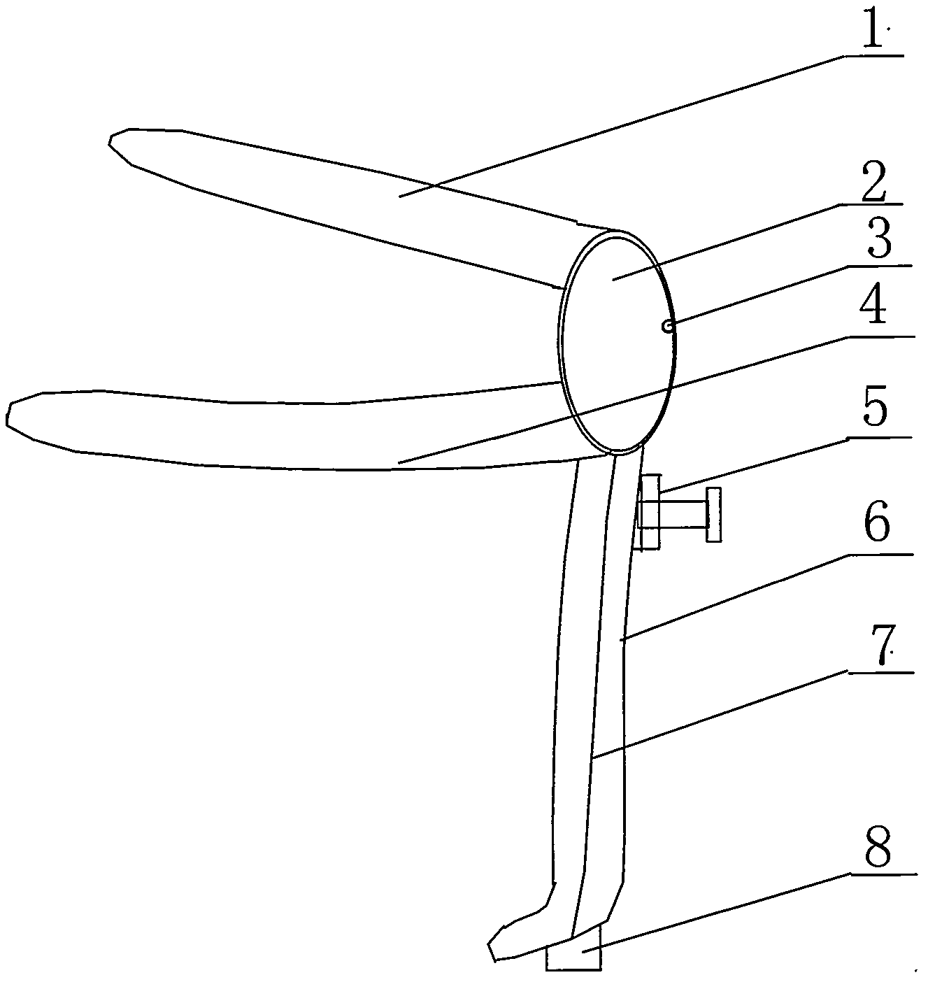
[0032] Such as figure 1 Shown, speculum with fiber optic lighting, made of stainless steel. It consists of an upper expansion piece 1, a lower expansion piece 4, a viewing hole 2, a handle 6, and an adjustment bolt 5. The handle 6 is provided with an optical fiber groove, and the optical fiber 7 is arranged along the optical fiber groove. Connection; the other end of the optical fiber 7 is provided with an optical fiber output end 3, and the optical fiber output end 3 is placed inside the middle of the viewing hole 2.

[0033] The method of use of the embodiment of the present invention is as follows: insert the expansion piece into the vagina, adjust the upper and lower expansion pieces to open the vagina, and tighten the adjusting bolt to fix it. The output end of the optical fiber emits light, and the doctor operates the handle to visit the tissue in the vagina through the viewing hole for inspection, operation and treatment. This embodiment is used in gynecological surge...

Embodiment 2

[0035] Dilator with fiber optic lighting, made of polystyrene. It consists of an upper expansion piece 1, a lower expansion piece 4 inspection hole 2, a handle 6, and an adjustment bolt 5. There is an optical fiber groove on the handle 6, and the optical fiber 7 is arranged along the optical fiber groove, and is connected to the coupler 8 at the end of the handle 6. ; The other end of the optical fiber 7 is provided with an optical fiber output end 3, and the optical fiber output end 3 is placed inside the middle of the viewing hole 2.

[0036] The method of use of this embodiment is as follows: Insert the dilator into the vagina, adjust the upper and lower dilators to open the vagina, and tighten the adjusting bolts to fix it. The output end of the optical fiber emits light, and the doctor operates the handle to view the tissue in the vagina through the viewing hole. This embodiment is used for gynecological examination and is disposable.


PUM


Abstract

The invention belongs to medical instruments, and discloses a vaginal dilator with an optical fiber illumination device. An existing vaginal dilator has the defects that the existing vaginal dilator only has the vagina expanding function and does not have the illumination function, so that inspection is not complete, treatment is not complete or the treatment is excessive, and at the same time, labor and a specialized power source are wasted. The vaginal dilator with the optical fiber illumination device comprises an upper expanding sheet (1), a lower expanding sheet (4), a watching hole (2), a handle (6) and an adjusting bolt (5), wherein an optical fiber groove is formed in the handle (6), optical fibers (7) are arranged along the optical fiber groove to the tail end of the handle (6) and then connected with a coupler (9), the other ends of the optical fibers are provided with an optical fiber output end (3), and the optical fiber output end (3) is arranged inside the middle portion of the watching hole (2). The vaginal dilator with the optical fiber illumination device has the advantages of not only having the vagina expanding function, but also having the illumination function, being capable of illuminating tissue inside a vagina precisely, enabling a doctor to conduct operating conveniently, improving gynecologic examination precision and operation cure rate, lowering energy consumption of operating room illumination, and saving manpower.

Description

technical field [0001] The invention belongs to medical instruments, in particular to a vaginal dilator with an optical fiber lighting device. Background technique [0002] Vaginal dilator - also known as vaginal dilator, vaginal speculum, speculum, vaginal speculum. It is mainly used for routine gynecological examination and surgery. The speculum used for surgery is usually made of metal materials; the speculum used for general gynecological examination is usually made of polystyrene, polypropylene and other materials. The vaginal dilator is composed of upper and lower expansion pieces, a handle and an adjusting bolt, and the size can be adjusted. The method of using the vaginal dilator is as follows: the doctor puts the dilator with the upper and lower dilator into the vagina, applies lubricant, slowly pushes it into the vagina until the dilator is pushed to the target position, and then puts the dilator up and down. Open it, adjust the bolt to fix the size, and then th...

Claims


Application Information

Patent Timeline
Patent Type & Authority Applications(China)
IPC IPC(8): A61B1/32A61B1/07
Inventor 马莉陶玙婧
Owner 马莉
Why Eureka
Try Eureka