Contact totally closed contactor

A fully enclosed, contactor technology, applied in relays, electromagnetic relays, electromagnetic relay details, etc., can solve problems such as damage to the contactor, affecting normal work, poor contact, etc., to reduce the cost of use and avoid the entry of dust and other impurities , the effect of eliminating security risks

Inactive Publication Date: 2013-08-14
田春
View PDF5 Cites 6 Cited by
  • Summary
  • Abstract
  • Description
  • Claims
  • Application Information

AI Technical Summary

Problems solved by technology

[0003] Due to the influence of the dynamic and static magnet structure of the traditional contactor, the contacts cannot be fully enclosed, so its technical defect is open, that is, the aforementioned electromagnetic system and contact system are not closed. The disadvantages of this structure are: first External impurities such as dust and dust are easy to enter and attach to the contacts. After a long period of use, a layer of dust will accumulate on the contacts, which may not only cause poor contact, but also increase the resistance between the contacts, resulting in a high If the rise exceeds the specified value, it will affect the normal work and even damage the contactor. If you want to clean the dust, you need to disassemble the contactor. The operation is quite troublesome; The arc extinguishing device cannot completely eliminate the risk of sparks igniting flammable and explosive gases such as gas, and there are certain safety hazards
Therefore, traditional contactors cannot be directly applied to places where flammable and explosive gases exist, and need to be installed with protective devices before they can be used. This will not only increase the additional cost of use, but also the protective effect is not ideal

Method used


Image

  • Contact totally closed contactor

Examples


Embodiment Construction

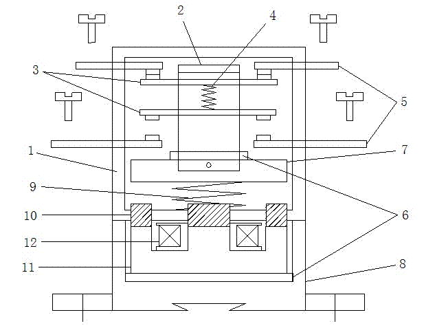
[0010] In this example, refer to figure 1 , the contact fully enclosed contactor includes a moving contact 3, a moving contact bracket 2, a moving contact spring 4, a static contact 5, an armature 7, a base 8, a buffer spring 9, a static iron core 11 and an electromagnetic The coil 12, the static iron core 11 is installed on the base 8, the electromagnetic coil 12 is installed on the static iron core 11, the armature 7 is arranged above the static iron core 11, the buffer spring 9 is fixed on the bottom surface of the armature 7, and the movable contact bracket 2 is fixed on the armature 7, the moving contact 3 is fixed on the moving contact bracket 2, and the static contacts 5 are respectively fixed on the upper and lower sides of the moving contact 3, and the two moving contacts 3 are connected by the moving contact spring 4; the moving contact A gasket 6 is provided between the bracket 2 and the armature 7, between the bottom surface of the static iron core 11 and the base ...


PUM


Abstract

The invention discloses a contact totally closed contactor which comprises movable contacts, a movable contact bracket, a movable contact spring, fixed contacts, an armature, a base, a buffer spring, a static iron core and electromagnetic coils, and further comprises a housing, wherein the movable contacts, the movable contact bracket, the movable contact spring, the armature and the buffer spring are sealed in the housing; one end of each of the fixed contacts extends into the housing, and the other end thereof extends out of the housing; a magnetic transitional iron core is arranged between the housing and the base; and the lower end of the magnetic transitional iron core penetrates the housing to be in contact with the static iron core, and the upper end penetrates the housing to be protruded below the armature. According to the invention, the movable contacts, the movable contact bracket, the movable contact spring, the armature and the buffer spring are sealed in the housing, the magnetic transitional iron core serves as a magnetic field conduction mechanism, so as to isolate the interior of the contactor from the outside, which in turn avoids entering of dusts and other impurities; and accordingly, the spark generated during contact of the contacts can not ignite methane gas and other inflammable and explosive gases so as to avoid potential safety hazards.

Description

technical field [0001] The invention relates to the technical field of electrical equipment, in particular to a contactor which functions as a switch and is applied in the fields of electric power, power distribution and power consumption. Background technique [0002] A contactor refers to an electrical appliance that uses an electromagnetic coil to flow through an electric current to generate a magnetic field to close the contacts in industrial electricity to control the load. A traditional contactor usually consists of an electromagnetic system (armature, static iron core, electromagnetic coil), a contact system (moving contact and static contact) and an arc extinguishing device. Because it can quickly cut off the AC and DC main circuits and can frequently connect to the high-current control circuit, it is often used as a control object for motors, and can also be used to control factory equipment, electric heaters, working machines and various electric power Units and o...

Claims


Application Information

Patent Timeline
Patent Type & Authority Applications(China)
IPC IPC(8): H01H50/02H01H50/58
Inventor 田春
Owner 田春
Why Eureka
Try Eureka