Oil and gas separator, engine and automobile
A technology of oil and gas separator and engine, which is applied in the direction of machines/engines, engine components, mechanical equipment, etc., can solve the problem of low oil and gas separation efficiency, and achieve the effect of improving oil and gas separation efficiency, increasing oil return efficiency, and smooth oil return
- Summary
- Abstract
- Description
- Claims
- Application Information
AI Technical Summary
Problems solved by technology
Method used
Image

Examples
Embodiment 1
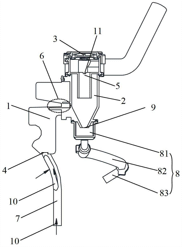
[0018] figure 1 Shown is a schematic structural diagram of the oil-gas separator in the embodiment of the present invention. Such as figure 1 As shown, the oil-gas separator in the embodiment of the present invention includes a separation cavity, and an air inlet 4 and an air outlet 5 are formed on the separation cavity. Gas separation, the separated gas is discharged from the gas outlet 5, and the oil droplets return to the oil pan through the oil return pipeline. Wherein, the separation chamber includes a first separation chamber 1 and a second separation chamber 2 that are airtightly connected, and a labyrinth baffle group 6 is arranged in the first separation chamber 1, and the area where the labyrinth baffle group 6 is located forms a labyrinth. Separation zone; the second separation chamber 2 includes a cyclone separation zone, thereby forming a secondary oil-gas separation structure. A first liquid outlet (not shown in the figure) and an air inlet 4 are formed on the...
Embodiment 2
[0026] Based on the same inventive concept, an engine is provided in an embodiment of the present invention. The oil-air separator of the engine adopts the oil-air separator in Embodiment 1. Since the oil-air separation efficiency of the oil-air separator is improved, the oil and gas in the crankcase of the engine are reduced. Emissions caused by oil and gas.
[0027] Wherein, by effectively utilizing the internal space of the engine cylinder block, the first oil return pipeline can be formed on the inner wall of the engine cylinder block, specifically, it can be molded together with the engine cylinder block through a casting process, which is beneficial to reduce the occupied space of the engine. Further, by connecting one end of the first oil return pipeline to the air inlet of the oil-gas separator in airtight communication, while the other end is used as the crankcase air intake, the length of the air intake passage of the oil-gas separator can be greatly increased, making...
Embodiment 3
[0031] At the same time, the embodiment of the present invention also provides an automobile. The engine of the automobile adopts the engine in the second embodiment, and the emission problem caused by oil and gas in the crankcase of the engine is reduced, thereby reducing the emission problem of the automobile.
[0032] It can be seen from the above embodiments that the oil-gas separator provided by the present invention includes a first separation chamber and a second separation chamber that are connected. A plurality of labyrinth baffle groups are arranged in the first separation chamber to form a labyrinth separation area; the second separation chamber includes a cyclone separation area to form a secondary oil-gas separation structure. Among them, the first liquid outlet and the air inlet of the oil-gas separator are formed on the first separation chamber, and the second liquid outlet and the gas outlet of the oil-gas separator are formed on the second separation chamber, s...
PUM
 Abstract
Description
Claims
Application Information
 - R&D
- Intellectual Property
- Life Sciences
- Materials
- Tech Scout
- Unparalleled Data Quality
- Higher Quality Content
- 60% Fewer Hallucinations
Browse by: Latest US Patents, China's latest patents, Technical Efficacy Thesaurus, Application Domain, Technology Topic, Popular Technical Reports.
© 2025 PatSnap. All rights reserved.Legal|Privacy policy|Modern Slavery Act Transparency Statement|Sitemap|About US| Contact US: help@patsnap.com