
Linear actuator and aircraft component comprising same

A technology of linear actuators and bearing parts, used in transmission parts, transmissions, aircraft transmissions, etc.

Inactive Publication Date: 2013-08-14
EADS AIRCRAFT DESIGN LTD
View PDF8 Cites 7 Cited by
  • Summary
  • Abstract
  • Description
  • Claims
  • Application Information

AI Technical Summary

Problems solved by technology

[0015] Another drawback is that, in both proposals, the unlocking of the output linear element is performed at the height of the nut of the screw

Method used


Image

  • Linear actuator and aircraft component comprising same
  • Linear actuator and aircraft component comprising same
  • Linear actuator and aircraft component comprising same

Examples


Embodiment Construction

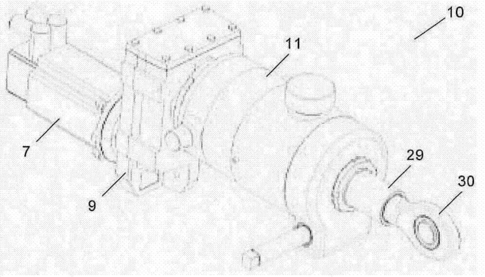
[0035] figure 1 An overview of a linear actuator 10 for linearly moving an actuator 30 according to an embodiment of the present invention, which will now be described, is shown.

[0036] For example, a set of linear actuators 10 may be used in order to actuate control surfaces of the aircraft.

[0037] The linear actuator 10 converts the rotational motion of an input shaft (driven by an electric motor 7 through a gearbox 9 ) located within a housing 11 into a controlled linear motion of an output shaft 29 to which an actuator 30 is connected. The linear actuator 10 may be directly driven by an electric motor.

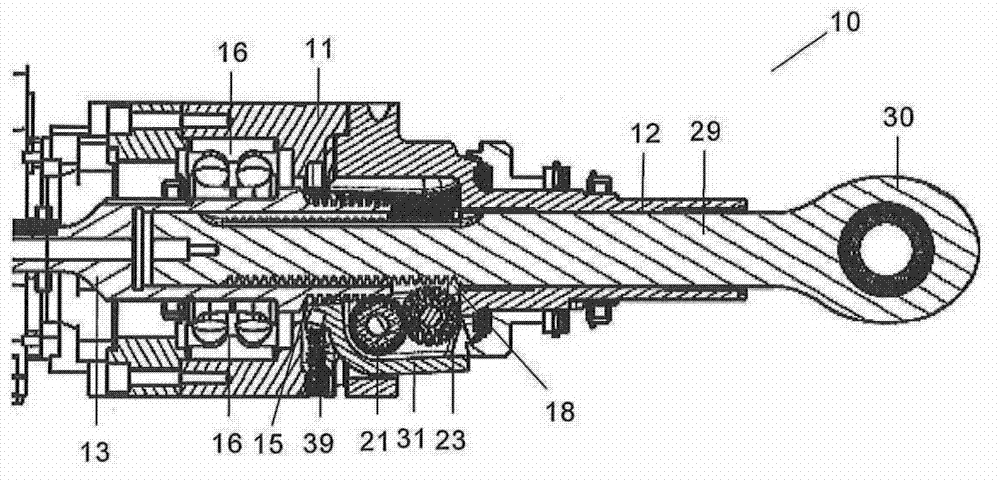
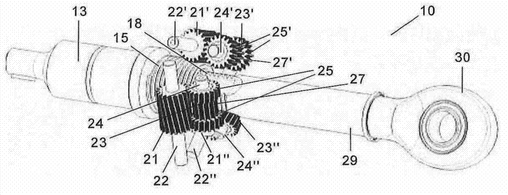
[0038] figure 2 with image 3 The main components of the linear actuator 10 are shown: input shaft 13, output shaft 29, three first helical roller gears 21, 21', 21" and three second helical roller gears 23, 23', 23" ( Although in image 3 Only the first roller gear 21, 21' and the second roller gear 23, 23' are clearly shown in the image 3 Corresponding refere...


PUM


Abstract

A linear actuator (10) comprising: - a rotatory input shaft (13) driven by an electric motor having a helical threaded zone (15) in its external surface at its inner end: - an output shaft (29) having a helical threaded zone (18) in its external surface at its inner end; - a plurality of first helical roller gears (21,21',21") configured to engage with the rotatory input shaft (13) in its helical threaded zone (15) so that they rotate with respect to their axis (22,22',22") when the input shaft (13) rotates; - a plurality of second helical roller gears (23,23',23") configured to engage with the first helical roller gears (21,21',21") and with the output shaft (29) in its helical threaded zone (18) so that the rotation of the first helical roller gears (21,21',21") is firstly transmitted to the second helical roller gears (23,23',23"), which rotate with respect to their axis (24,24',24"), and secondly converted in a linear movement of the output shaft (29).

Description

technical field [0001] The present invention relates to an electromechanical actuator, and more particularly, to an electromechanical actuator capable of functioning in the event of obstruction of its internal mechanical components. Background technique [0002] Linear actuators are used in a variety of industrial products. In the aviation industry, in particular as actuators for aircraft control surfaces and other aircraft components. [0003] Typically, each aircraft control surface is actuated by a plurality of linear actuators connected in parallel, so that in the event of a loss of energy in one of them, this surface can be controlled by the remaining actuators. Since this configuration has the disadvantage that a blockage of one actuator may produce a blockage of the surface, aviation regulations require a very low probability of blockage (class of 10e-9) for said actuator. Hydraulic actuators can meet this requirement. [0004] A trend towards greater electrificati...

Claims


Application Information

Patent Timeline
Patent Type & Authority Applications(China)
IPC IPC(8): B64C13/50B64C13/28
CPCY02T50/44B64C13/42F16H2057/0081F16H1/16F16H19/04Y02T50/54B64C13/50F16H2057/018Y10T74/18096F16H19/00Y02T50/40Y02T50/50
Inventor 弗洛瑞斯·吉拉尔杜·圣地亚哥费尔南德斯·加西亚·弗朗西斯科·哈维尔
Owner EADS AIRCRAFT DESIGN LTD
Learn More