
Control algorithm of automotive magneto-rheological semi-active suspension system and real-time optimal current

A technology of semi-active suspension and control algorithm, applied in suspension, elastic suspension, vehicle parts, etc., can solve problems such as failure to give

Inactive Publication Date: 2015-05-13
SHANDONG UNIV OF TECH
View PDF5 Cites 1 Cited by
  • Summary
  • Abstract
  • Description
  • Claims
  • Application Information

AI Technical Summary

Problems solved by technology

Although many vehicle suspension research experts at home and abroad have done a lot of research on the magneto-rheological semi-active suspension of automobiles, due to the constraints of the real-time optimal damping ratio of the semi-active suspension system and the identification of the current driving road conditions of the vehicle, it has not been possible to give a comprehensive analysis of the current driving conditions of the vehicle. The real-time optimal current control algorithm of automotive magneto-rheological semi-active suspension under different driving conditions can be seen from the research data. The research on the strategy and control method, for the current control law of the magneto-rheological shock absorber of the semi-active suspension of the automobile, is mostly obtained through test fitting.

Method used


Image

  • Control algorithm of automotive magneto-rheological semi-active suspension system and real-time optimal current
  • Control algorithm of automotive magneto-rheological semi-active suspension system and real-time optimal current
  • Control algorithm of automotive magneto-rheological semi-active suspension system and real-time optimal current

Examples


Embodiment 1

[0034] Embodiment one: the sprung mass m of certain automobile single-wheel suspension 2 =300kg, suspension stiffness k 2 =13057N / m, unsprung mass m 1 = 40kg, tire stiffness k t =192000N / m; the inner diameter of the piston cylinder of the magneto-rheological shock absorber is D H =28mm, piston rod diameter d g =18mm, the annular gap between the piston and the inner cylinder h=1.0mm, the diameter of the piston D p =D H -2h=26mm, piston length L=40mm; suspension lever ratio i=0.9 and shock absorber installation angle θ=10°; the initial viscosity of the magnetorheological fluid is 0.8Pa.s when no external magnetic field is applied, and the magnetorheological fluid The magnetic shear stress coefficient K τ = 0.0015, the magnetic field strength index of the magnetic shear stress α = 1.6; suspension dynamic deflection limit stroke [f d ] = 0.1 m. The measured body motion speed u 2 =0.2m / s, wheel speed u 1 =-0.1m / s, vehicle speed v=40km / h, vehicle body vibration acceleratio...

Embodiment 2

[0063] Embodiment 2: The vehicle is the same as Embodiment 1, that is, vehicle parameters, suspension parameters, suspension dynamic deflection limit stroke, structural parameters of the magnetorheological shock absorber, characteristic parameters of the magnetorheological fluid, and number of turns of the electromagnetic coil. Exactly the same as that of embodiment one; Just the measured vehicle speed v, vehicle body vibration acceleration during driving Body up and down movement speed u 2 , Wheel up and down movement speed u 1 , and the magneto-rheological shock absorber electromagnetic coil current I 'is different from that of embodiment one; wherein, the measured vehicle body motion speed u 2 =0.35m / s, wheel speed u 1 =0.1m / s, vehicle speed v=60km / h, vehicle body vibration acceleration Current magneto-rheological shock absorber electromagnetic coil current I'=0.45A. The current road condition G of the car q (n 0 ) to identify, and calculate the real-time optimal co...

Embodiment 3

[0092] Embodiment three: a semi-active suspension system of a certain automobile, except that the sprung mass and suspension stiffness are different from those in embodiment one, other parameters and the signals measured during driving are all identical to those in embodiment one; The sprung mass of the single wheel of the car m 2 =400kg, suspension stiffness k 2 =20884N / m; the current road condition G of the vehicle q (n 0 ) to identify, and calculate the real-time optimal control current I of the magneto-rheological shock absorber electromagnetic coil under the current driving condition.

[0093] Using the design steps of Embodiment 1, the control current I of the magneto-rheological shock absorber electromagnetic coil is calculated, namely:

[0094] (1) The current damping coefficient C′ of the semi-active suspension system of the vehicle d And the real-time simulation calculation of the damping ratio ξ':

[0095] According to the structural parameters of the shock abs...


PUM


Abstract

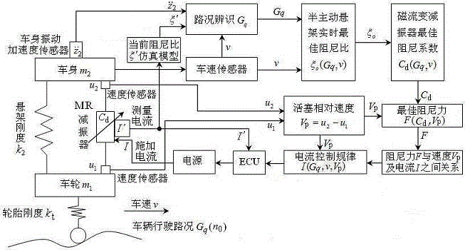
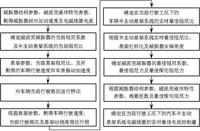
The invention relates to a control algorithm of an automotive magneto-rheological semi-active suspension system and real-time optimal current, and belongs to the technical field of dampers. The control algorithm is characterized by comprising the steps that damping characteristics of a magneto-rheological damper and the semi-active suspension system are simulated according to the currently measured current; the current running road condition of an automobile is identified according to the running speed and the vibration acceleration of an automobile body; a real-time optimal damping ratio of the semi-active suspension system and an optimal Coulomb damping force of the magneto-rheological damper are determined according to the current running road condition, and speed and suspension parameters; and the real-time optimal control current of the automotive magneto-rheological semi-active suspension under the current running working condition is calculated according to relations among the Coulomb damping force, a structure parameter, a magneto-rheological liquid characteristic parameter, the turn number of an electromagnetic coil and the current. According to the control algorithm, a design level and the performances of the magneto-rheological semi-active suspension system can be raised and improved; design and testing expenses are lowered; and the running smoothness and the safety of the automobile are improved.

Description

technical field [0001] The invention relates to a magneto-rheological semi-active suspension system, in particular to a real-time optimal current control algorithm for an automobile magneto-rheological semi-active suspension system. Background technique [0002] The magneto-rheological shock absorber can control the damping force by controlling the magnitude of the current. It has the characteristics of fast response, low power consumption, large adjustment range, etc., and the working conditions are relatively simple. It has become the current domestic and foreign vehicle semi-active A hot spot in the field of suspension research. The magnitude of the electromagnetic coil current I determines the damping characteristics of the magnetorheological shock absorber and the damping matching of the semi-active suspension system, which has an important impact on the ride comfort of the vehicle. Although many vehicle suspension research experts at home and abroad have done a lot of...

Claims


Application Information

Patent Timeline
Patent Type & Authority Patents(China)
IPC IPC(8): B60G17/015B60G17/06
Inventor 周长城李红艳汪晓
Owner SHANDONG UNIV OF TECH
Learn More