
Semi-active shock absorber control system

a control system and semi-active technology, applied in the direction of shock absorbers, instruments, cycle equipment, etc., can solve the problems of large shock loads, degraded isolation performance, and inability to achieve large shock loads

Inactive Publication Date: 2005-06-07
GENERAL KINETICS ENG CORP
View PDF33 Cites 41 Cited by
  • Summary
  • Abstract
  • Description
  • Claims
  • Application Information

AI Technical Summary

Benefits of technology

[0010]The present invention solves the shortcomings of the prior art with a set

Problems solved by technology

However if the mass changes due to increased payload, or the input frequency changes due to a change in speed over the ground, the isolation performance is degraded and often results in very large shock loads when the system hits the ends of travel, usually referred to as “topping” or “bottoming” the suspension.
Active suspensions have not gained wide acceptance due to high cost and complexity as well as the demand for high power from the vehicles prime mover.
In the case of off-road vehicles with long travel suspensions moving over rough terrain, the power draw of the suspension is prohibitive and reduces the maximum acceleration of the vehicle.
While this method can yield very good isolation over bumps that are smaller than the amount of compression travel in the system, larger bumps cause the suspension to bottom out resulting in a large shock load being transmitted into the sprung mass.
While this is effective in preventing the high shock loads from being transmitted into the sprung mass, it results in excessive suspension movement over smaller bumps.
This can be very disconcerting to the operator because it prevents him from having a good “feel” for the behavior and handling of the vehicle.

Method used


Image

  • Semi-active shock absorber control system
  • Semi-active shock absorber control system
  • Semi-active shock absorber control system

Examples


Embodiment Construction

[0030]Before describing the present invention in detail, the following definitions shall be used throughout the Detailed Description.

Definitions

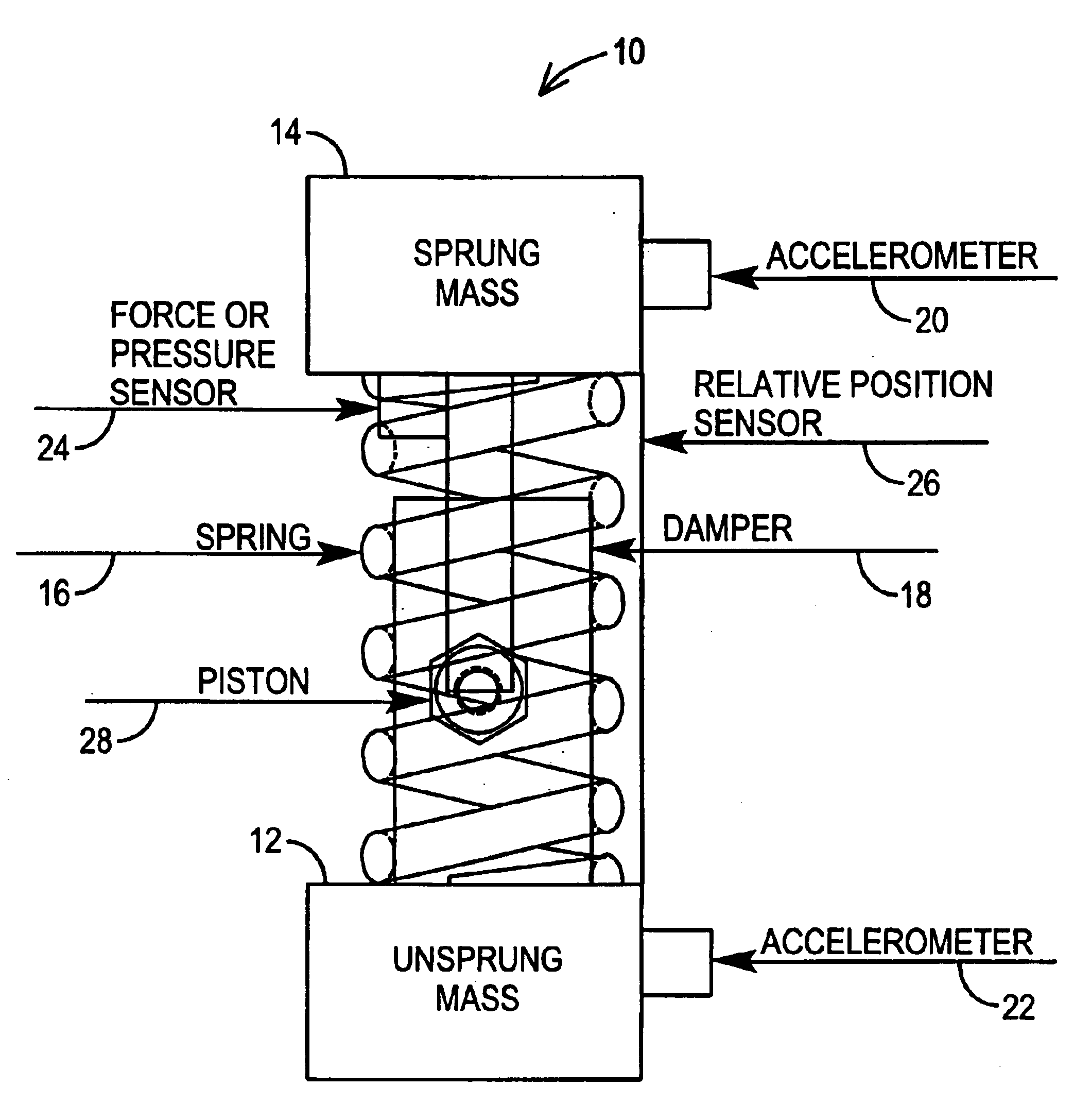
[0031]Sprung Mass (SM)—A sprung mass, in the case of a car it would be the car chassis, in the case of a truck seat, it would be the seat and passenger.[0032]Unsprung Mass (USM)— An unsprung mass, in the case of a car it would be the wheel; in the case of a truck seat it would be the truck.[0033]Relative Position (Xrel)— means the position of the sprung mass (SM) and the unsprung mass (USM) relative to one another.[0034]Relative Velocity (Vrel)— means the velocity of the SM and USM relative to one another.[0035]Bump Stop—Position of physical constraint that limits the minimum possible relative position of the masses.[0036]Droop Stop—Position of physical constraint that limits the maximum possible relative position of the masses.[0037]Endstop—means either the droop stop or bump stop or both.[0038]Xend—is a constant for a given system and repr...


PUM


Abstract

A semi-active control methodology is provided for a spring / mass system, for example a real-time adjustable shock absorber system. The methodology includes defining a plurality of operating zones based on system parameters and user-definable or preset inputs. The methodology also includes processing to account for non-inertial spring / mass system response and multidimensional forces acting on the system, and an acceleration hedge calculation to accurately define system operation at extrema of travel. The methodology is generally directed at producing a plurality of valve control signals, selecting among the valve control signals, and applying the selected control signal to the valve in a closed-loop feedback system to adjust the energy in the spring / mass system.

Description

[0001]This application is a continuation application under 37 CFR § 1.53(b) of application Ser. No. 10 / 341,129 filed Jan. 13, 2003, now U.S. Pat. No. 6,732,033, which claims priority to U.S. Provisional Application Ser. No. 60 / 347,662, filed Jan. 11, 2002, both of which are incorporated herein by reference.[0002]The U.S. Government has a paid-up license in this invention and the right in limited circumstances to require the patent owner to license others on reasonable terms as provided for by the terms of Contract Number USZA22-02-P-0024 awarded by the Department of Defense.1. FIELD OF THE INVENTION[0003]The present invention relates to a controller and control methodology for a semi-active shock absorber. More particularly, the present invention relates to a system and method of controlling the relative motion between two masses, using a suspension that includes a shock absorber or damper. The system and method can be applied to a number of types of systems such as the primary susp...

Claims


Application Information

Patent Timeline
IPC IPC(8): B60G17/08B60G17/06F16F7/10F16F15/02B60G23/00
CPCB60G17/08F16F15/022F16F7/1005B60G2400/102B60G2400/104B60G2400/202B60G2400/252B60G2600/02B60G2600/09B60G2600/11B60G2600/184B60G2500/10F16F15/023B60G17/015
Inventor LAPLANTE, JOHN A.LARKINS, WILLIAM T.
Owner GENERAL KINETICS ENG CORP
Learn More