
Mould for plastic container

A technology for plastic containers and molds, applied in the field of molds for plastic containers, can solve the problems of deformation of plastic parts, difficult demoulding action, unreliability, etc., and achieve the effects of improving performance, improving injection molding production efficiency, and improving surface quality.

Active Publication Date: 2013-08-14
LONGYUAN IND SHANTOU CITY
View PDF4 Cites 1 Cited by
  • Summary
  • Abstract
  • Description
  • Claims
  • Application Information

AI Technical Summary

Problems solved by technology

However, in the actual injection molding production practice, it is unreliable to rely solely on compressed air for demoulding, especially for plastic containers with deep inner cavities, it is often difficult to successfully complete the demoulding action; The cavity injects compressed air directly into the joint between the top of the core and the product. The compressed air directly impacts a certain part of the plastic product just out of the mold, which is easy to deform or damage the plastic product.

Method used


Image

  • Mould for plastic container

Examples


Embodiment 1

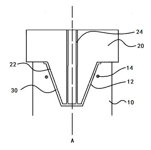
[0018] Such as figure 1 As shown, the mold for the plastic container described in this embodiment, the ratio of the depth of the plastic container to the bottom diameter of the container is equal to 2, and it includes a movable mold 10 with a cavity 12 and a fixed mold 20 containing a core 22 , the core 22 is in a convex shape corresponding to the inner surface of the plastic container, the cavity 12 is in a concave shape corresponding to the outer surface of the plastic container, and the cavity 12 and the core 22 meet to form the shape of the plastic container molding cavity 30, and the fixed mold 20 has a vertical injection pipe 24 extending from its upper surface to its lower surface, and the movable mold 10 has a magnetic induction heating coil 14 along the periphery near the top of the cavity 12 . Wherein the movable mold and the fixed mold are casted by self-lubricating alloy steel, and the chemical composition of the self-lubricating alloy steel is as follows: 0.20wt%...


PUM

PropertyMeasurementUnit
Tensile strengthaaaaaaaaaa
Thicknessaaaaaaaaaa

Abstract

The invention relates to a mould of a plastic container. The ratio value of the depth of the plastic container to the diameter of the bottom of the container is more than 1.5. The mould comprises a movable mould with a mould cavity and a fixed mould with a mould core, wherein the mould core is in a convex shape corresponding to the inner surface of the plastic container; the mould cavity is in a concave shape corresponding to the outer surface of the plastic container; a molding cavity of the plastic container is formed by combining the mould cavity and the mould core; the fixed mould is provided with a vertical injection molding pipeline which extends to the lower surface from the upper surface of the fixed mould; and the movable mould is provided with a magnetic induction heating coil along the periphery of the mould cavity. According to the mould of the plastic container disclosed by the invention, the direct injection molding of the plastic container with a high length-diameter ratio can be realized; and the performance of injection molding and de-molding of the plastic container can be effectively improved, the time required for de-molding is shortened and the injection molding production efficiency is improved; and the surface quality of the plastic container is improved.

Description

technical field [0001] The invention relates to the technical field of moulds, and more specifically, the invention relates to a mold for plastic containers. Background technique [0002] Plastic containers are usually manufactured using injection molds and injection molding processes, but for plastic containers with a certain depth, it will not only cause difficulty in demoulding or poor surface quality due to uneven temperature distribution in the depth direction of injection-molded plastic containers. In the prior art, compressed air is used for demoulding. Usually, a valve cavity is set in the middle of the core. After the injection molding is completed and the movable mold and the fixed mold are separated, compressed air is injected into the joint between the top of the core and the product, and the air pressure is used to release the mold. The product pops up. However, in the actual injection molding production practice, it is unreliable to rely solely on compressed ...

Claims


Application Information

Patent Timeline
IPC IPC(8): B29C45/26B29C45/40B29C45/83
Inventor 李亨群
Owner LONGYUAN IND SHANTOU CITY
Learn More