
Shaft seal of oil seal machinery

A mechanical shaft and oil sealing technology, applied in the direction of mechanical equipment, engine seals, engine components, etc., can solve the problems of dry grinding, short service life of materials, easy leakage, etc., to overcome the phenomenon of dry grinding, simple structure, and low cost Effect

Inactive Publication Date: 2013-08-07
方高云
View PDF9 Cites 3 Cited by
  • Summary
  • Abstract
  • Description
  • Claims
  • Application Information

AI Technical Summary

Problems solved by technology

[0002] At present, the shaft seal is generally composed of a shaft seal chamber, a shaft seal spring, a guide ring, an O-ring, a dynamic friction ring, a gasket, and a static friction ring. The sealing principle of the shaft seal is the principle of air sealing. It is a dynamic friction ring, and the material of the static friction ring is silicon carbide. Once the shaft is turned on at a high speed, the temperature of the end surface of the shaft seal will increase rapidly, which may cause the end surfaces of the dynamic ring and the static ring to burn red, and the oil will freeze after 10 seconds of starting the machine. At this time, the cold oil is sprayed to the red-hot sealing surface, and the temperature is rapidly cooled, which makes the graphite ring and the silicon carbide sealing surface swell, which is easy to cause the rupture of the sealing end surface, and the service life of the material is short
[0003] At the same time, if the shaft seal structure is air-tight, because the sealing gas working medium is Freon, the structure of Freon is a kind of easy-leakage molecule. Once the working time is long, it will be easy to leak, which will affect the stability and reliability of the refrigeration system.
[0004] At each startup, it takes more than 30 seconds for the oil to reach the shaft seal, resulting in dry grinding at that time, and if the speed is high, the shaft seal will be burned

Method used


Image

  • Shaft seal of oil seal machinery
  • Shaft seal of oil seal machinery

Examples


Embodiment Construction

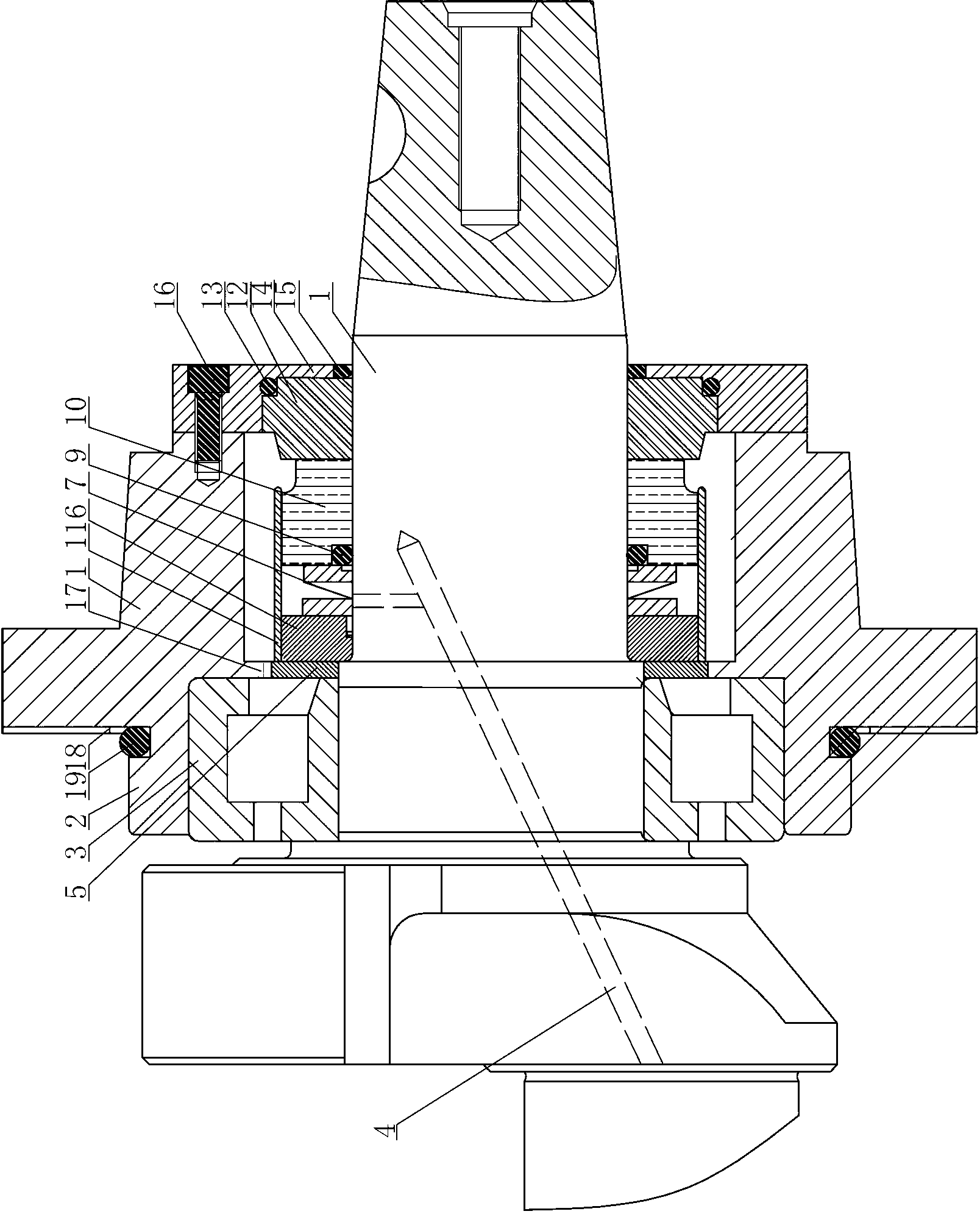
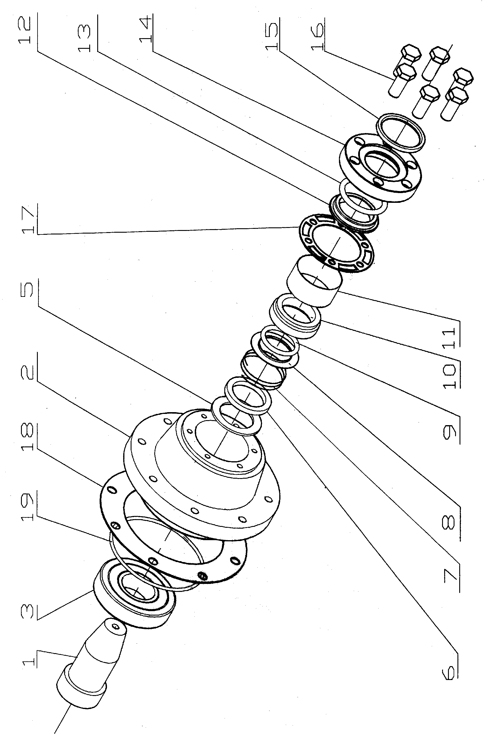
[0014] Depend on Figure 1 to Figure 2 It can be seen that the present invention includes crankshaft 1, front bearing housing 2, dynamic friction ring assembly and static friction ring assembly, wherein:

[0015] The middle of the front bearing seat 2 is a cavity, and the crankshaft 1 is interspersed in the cavity of the front bearing seat 2 through the bearing 3. There is an oil passage 4 in the shaft, and an oil baffle plate 5 is arranged on the right end surface of the bearing 3 to prevent oil The inner diameter surface of the plate 5 is attached to the crankshaft 1, the right end of the oil baffle plate 5 is provided with a dynamic friction ring assembly, and the right end of the dynamic friction ring assembly is provided with a static friction ring assembly, and the oil baffle plate 5 and the static friction ring assembly are in the cavity of the front bearing housing 2 form an annular oil pool;

[0016] The oil outlet of the above-mentioned oil passage 4 is opened on th...


PUM


Abstract

The invention relates to a shaft seal of oil seal machinery. The shaft seal comprises a crankshaft, a front bearing seat, a movable friction ring component and a fixed friction ring component, wherein the middle of the front bearing seat is a cavity; the crankshaft which is internally provide with an oil path is arranged in the cavity of the front bearing seat in an insertion manner through a bearing; an oil baffle is arranged at the right end face of the bearing; the inner radial surface of the oil baffle is stuck with the crankshaft; the movable friction ring component is arranged at the right end of the oil baffle; the fixed friction ring component is arranged at the right end of the movable friction ring component; the oil baffle and the fixed friction ring component form an annular oil pond in the cavity inside the front bearing seat; an oil outlet of the oil path is formed at the sidewall of the crankshaft; oil discharged by the oil outlet enters into the oil pond; steps which protrude inwards is arranged at the inner wall of the cavity of the front bearing seat; the outer diameter surface of the oil baffle is stuck with the step surface; and at least two through holes for discharging oil are arranged at the steps at the upper part. The shaft seal of the oil seal machinery has long service life, low cost and no leakage.

Description

technical field [0001] The invention relates to a shaft seal device, in particular to an oil-sealed mechanical shaft seal. Background technique [0002] At present, the shaft seal is generally composed of a shaft seal chamber, a shaft seal spring, a guide ring, an O-ring, a dynamic friction ring, a gasket, and a static friction ring. The sealing principle of the shaft seal is the principle of air sealing. It is a dynamic friction ring, and the material of the static friction ring is silicon carbide. Once the shaft is turned on at a high speed, the temperature of the end surface of the shaft seal will increase rapidly, which may cause the end surfaces of the dynamic ring and the static ring to burn red, and the oil will freeze after 10 seconds of starting the machine. At this time, the cold oil is sprayed to the red-hot sealing surface, and the temperature is rapidly cooled, which makes the graphite ring and the silicon carbide sealing surface swell, which is easy to cause th...

Claims


Application Information

Patent Timeline
Patent Type & Authority Applications(China)
IPC IPC(8): F16J15/18F16J15/24F16J15/40
Inventor 方高云
Owner 方高云
Learn More