Structure for cooling engine silencer

An engine and muffler technology, applied in the direction of engine cooling, engine components, machines/engines, etc., can solve the problems of reducing the service life of the engine, wear of core components, etc., to reduce the temperature of the whole machine, reduce the temperature, and improve the service life. Effect

Active Publication Date: 2015-03-04
SHANDONG HUASHENG PESTICIDE APPL MACHINERY CO LTD
View PDF6 Cites 0 Cited by
  • Summary
  • Abstract
  • Description
  • Claims
  • Application Information

AI Technical Summary

Problems solved by technology

[0002] At present, my country's emission regulations require low-emission engine mufflers to contain catalysts. When the catalyst is cracked, the fuel will be fully combusted, thereby greatly reducing a large number of harmful components contained in the exhaust gas and reducing air pollution. However, a large amount of heat will be generated during combustion, resulting in noise reduction. The temperature of the engine and even the whole engine is too high. If the temperature is not cooled in time, the core components will wear out quickly, which will seriously reduce the service life of the engine. At present, the small fan of the engine is used to cool itself, but many engines cannot meet the needs of timely cooling. Therefore, , there is an urgent need for a structure that can quickly cool the engine muffler

Method used


Image

  • Structure for cooling engine silencer
  • Structure for cooling engine silencer
  • Structure for cooling engine silencer

Examples


Embodiment Construction

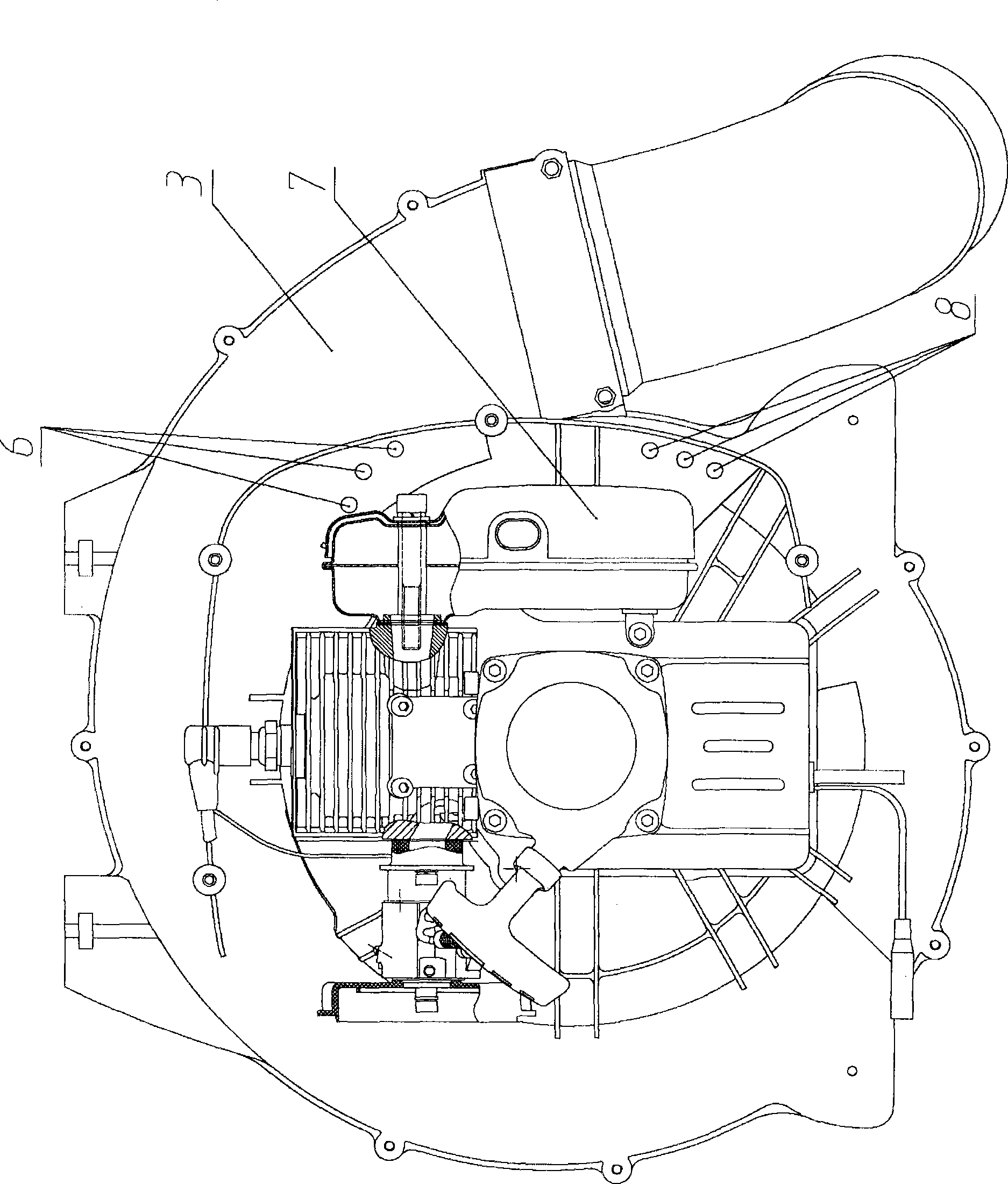
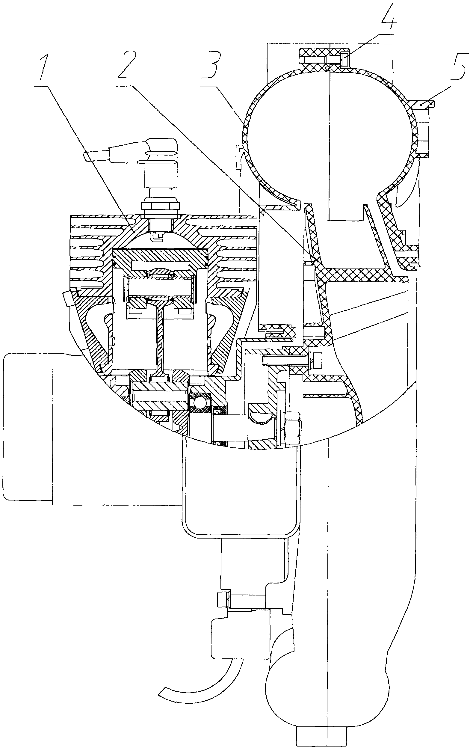
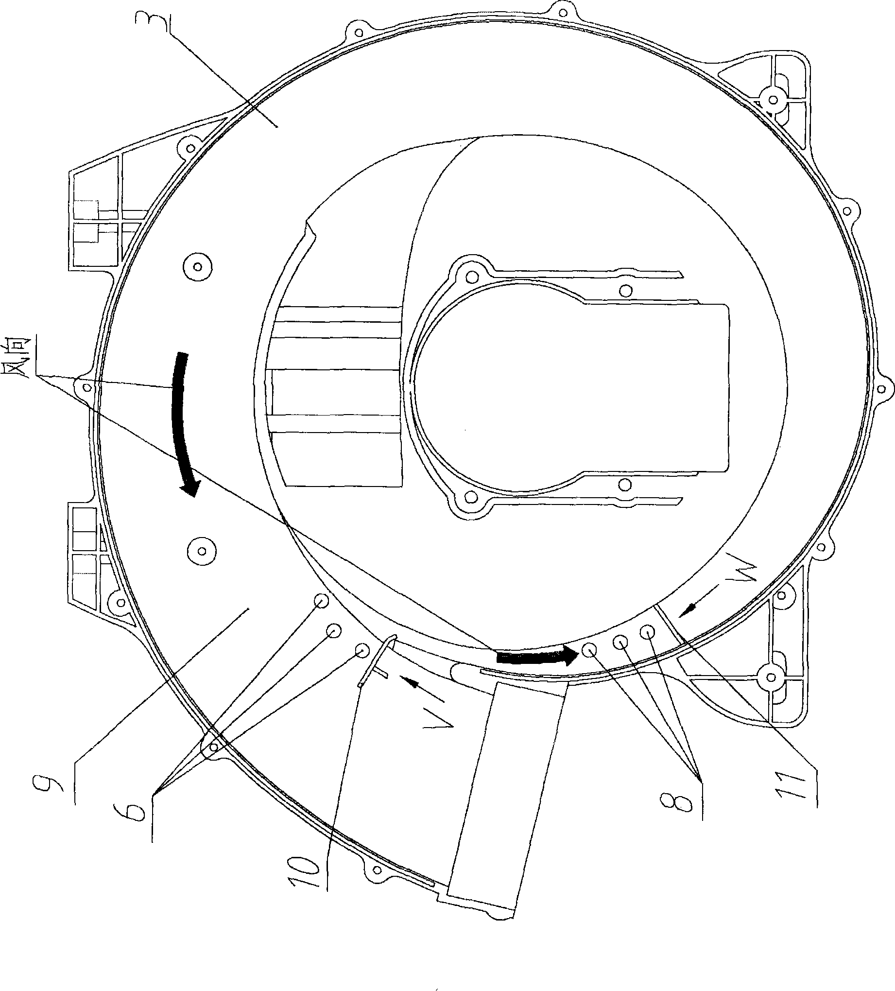
[0016] Such as figure 1 , figure 2 , image 3 , Figure 4 , attached Figure 5 Shown, the present invention scheme is by engine 1 (muffler 7), front half blower fan volute 3 (upper draft hole 6, lower draft vent 8, volute 9, upper windshield 10, lower windshield 11), The second half fan volute 5 and impeller 2 are formed.

[0017] The impeller 2 is placed in the volute 9 formed by the combination of the front half fan volute 3 and the back half fan volute 5, the front half fan volute 3 and the back half fan volute 5 are connected by fastening screws 4, and the impeller 2 is connected with the engine 1.

[0018] The upper air-introduction hole 6, the lower air-introduction hole 8, the upper windshield 10, and the lower windshield 11 are all on the front half fan volute 3, and the upper air-induction hole 6 and the lower air-induction hole 8 are multiple. The air hole 6 is positioned at the position close to the upper half of the muffler 7 on the front half fan volute 3 , ...


PUM


Abstract

The invention discloses a structure for cooling an engine silencer. The structure comprises an engine, a front half fan volute, a rear half fan volute and an impeller. The structure is characterized in that an induced air hole is arranged on the front half fan volute near the silencer and a wind shield is arranged on an inner wall of the front half fan volute positioned on one side of the induced air hole. The structure has the advantages that high-speed air flow flowing through a positive pressure area of a fan volute is blocked through the wind shield so that the high-speed air flow blows out through the induced air hole to cool the upper half part of the silencer, a lower wind shield blocks the high-speed air flow flowing through the positive pressure area of the fan volute so as to enable the high-speed air flow to blow out through a lower induced air hole to cool the lower half part of the silencer, the silencer can be cooled rapidly, temperature of the silencer is lowered, so that temperature of the whole engine is greatly reduced, and service life of the engine is greatly prolonged.

Description

technical field [0001] The patent of the present invention relates to the field of engine technology, in particular to a structure for cooling the engine. Background technique [0002] At present, my country's emission regulations require low-emission engine mufflers to contain catalysts. When the catalyst is cracked, the fuel will be fully combusted, thereby greatly reducing a large number of harmful components contained in the exhaust gas and reducing air pollution. However, a large amount of heat will be generated during combustion, resulting in noise reduction. The temperature of the engine and even the whole engine is too high. If the temperature is not cooled in time, the core components will wear out quickly, which will seriously reduce the service life of the engine. At present, the small fan of the engine is used to cool itself, but many engines cannot meet the needs of timely cooling. Therefore, , be badly in need of a kind of structure that can quickly cool down eng...

Claims


Application Information

Patent Timeline
Patent Type & Authority Patents(China)
IPC IPC(8): F01P3/12F01P5/02F04D29/42
Inventor 李帅刘向峰冯超刘飞黄进光唐立春邵逸群张士志
Owner SHANDONG HUASHENG PESTICIDE APPL MACHINERY CO LTD
Why Eureka
Try Eureka