Low-speed multipole synchronous generator

A synchronous generator and multi-pole technology, which is applied to synchronous machines, synchronous motors with stationary armatures and rotating magnets, electric components, etc., can solve the problems of unallowable use of generators and complicated manufacturing

Inactive Publication Date: 2013-07-31
维克多·芬多诺维奇·切乎诺夫 +1
View PDF5 Cites 2 Cited by
  • Summary
  • Abstract
  • Description
  • Claims
  • Application Information

AI Technical Summary

Problems solved by technology

[0003] However, such an engine has a large mass and size, is complex to manufacture, and has a current frequency of 50 Hz, which can only be achieved when the rotor rotates at high speed, which is not allowed for the use of generators in the design of wind turbines

Method used


Image

  • Low-speed multipole synchronous generator
  • Low-speed multipole synchronous generator
  • Low-speed multipole synchronous generator

Examples


Embodiment Construction

[0023] The present invention will be described in further detail below in conjunction with the accompanying drawings.

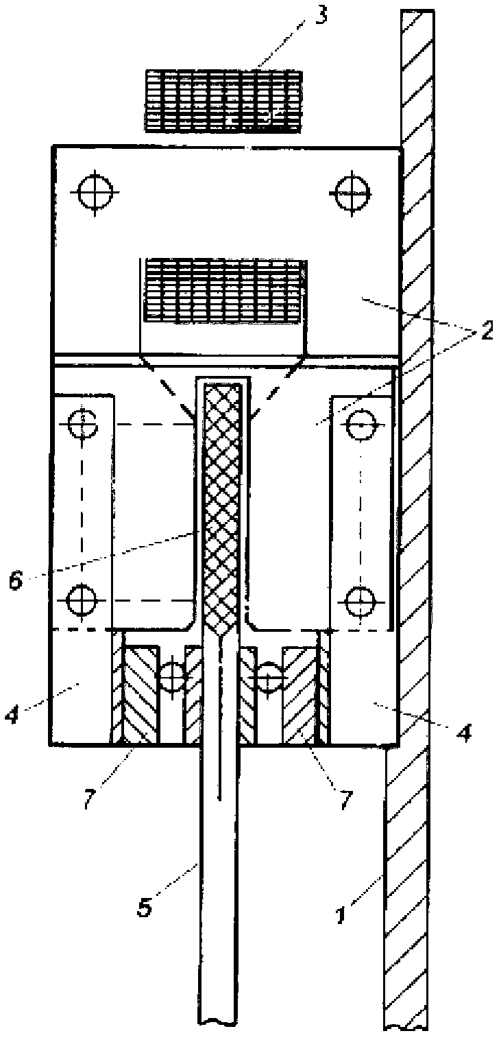
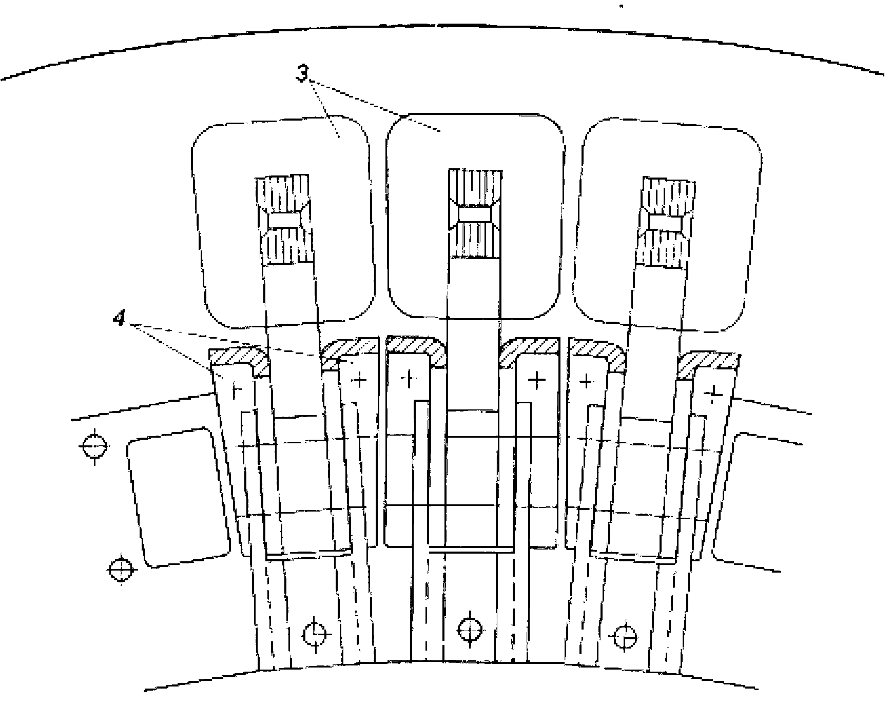
[0024] The low-speed multi-pole synchronous generator includes a housing 1 on which a stator 2 with a stator coil 3 is fixed, and the stator coil 3 is wound on an n-shaped magnetic conductor 4 .

[0025] On the shaft of the low-speed multipole synchronous generator (shaft not shown in the figure) is fixed a rotor 5 made in the form of a disc with inserts made of permanent magnets 6 . The permanent magnets 6 are installed in the rotor 5 alternately with respect to the direction of magnetization. At this time, the permanent magnets 6 are installed on the rotor 5 in such a way that the magnetizers 4 of the stator coils 3 are displaced circumferentially, that is, every 10th permanent magnet 6 or the magnetizers 4 of the stator coils 3 are arranged opposite to each other, so that Whichever is the most shall prevail. This ratio ensures a reduction in movement for...


PUM


Abstract

The invention relates to a low-speed multipole synchronous generator comprising a stator in the form of n-shaped segments with a winding formed from stator coils provided with one coil per pole and combined into different coil groups, as well as a rotor with permanent magnets arranged on the rim along the rotor. The rotor is in the form of a disk with inserts consisting of permanent magnets fixed alternately relative to the direction of magnetization, wherein the permanent magnets on the rotor are mounted with a circumferential shift relative to the yokes of the stator coils in such a way that every 10th magnet or yoke of the stator coil is arranged opposite one another depending on which poles there are more of.; The proposed synchronous generator has a significantly lower mass in comparison with the prior-art technical solution.

Description

technical field [0001] The invention relates to electrical engineering, in particular to the design of a low-speed multi-pole synchronous generator, and in particular can be widely used in the design of wind turbines. Background technique [0002] Magnetoelectric generators comprising a stator and a segmented rotor are known (cf. А.с.СССР No. 861716). The stator has a three-phase winding made of coils arranged one coil per pole and combined into different coil groups. The rotor has permanent magnets which are arranged on a yoke along the rotor axis. [0003] However, such an engine has a large mass and size, is complicated to manufacture, and has a current frequency of 50 Hz, which can only be achieved when the rotor rotates at a high speed, which is not allowed for the use of the generator in the design of a wind turbine. [0004] The closest to the present invention is a low-speed multi-pole synchronous generator (see Ukrainian Invention Patent Publication No.42513, publ...

Claims


Application Information

Patent Timeline
Patent Type & Authority Applications(China)
IPC IPC(8): H02K21/12H02K1/27
CPCH02K7/1838H02K21/185H02K21/24H02K7/183
Inventor 维克多·芬多诺维奇·切乎诺夫亚历山大·伊万诺维奇·科斯恩克依
Owner 维克多·芬多诺维奇·切乎诺夫
Why Eureka
Try Eureka