
Novel spiral bushing and reverser thereof

A commutator and screw technology, applied in the field of a new type of spiral bushing and its commutator, can solve the problems that the processing performance needs to be improved, the commutator is easy to move, and the performance of the commutator is affected, so as to prevent the axial and Radial movement, good processing performance, and cost reduction effect

Inactive Publication Date: 2013-07-31
HUARUI ELECTRICAL APPLIANCE
View PDF8 Cites 0 Cited by
  • Summary
  • Abstract
  • Description
  • Claims
  • Application Information

AI Technical Summary

Problems solved by technology

However, the processing performance of this bush needs to be improved, and it is easy to move in the commutator, thus affecting the performance of the commutator

Method used


Image

  • Novel spiral bushing and reverser thereof
  • Novel spiral bushing and reverser thereof
  • Novel spiral bushing and reverser thereof

Examples


Embodiment

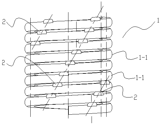
[0024] Embodiment: the novel spiral bushing of this embodiment is as figure 1 , 2 As shown in , 3, it includes a helical bushing body 1 formed by a plurality of helical coils 1-1. A plurality of bosses 2 forming gaps between adjacent helical turns 1-1.

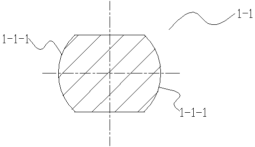
[0025] The spiral coil 1-1 is made of cold-rolled steel wire. The cross-section of the cold-rolled steel wire includes two convex arc-shaped sides 1-1-1, that is, the side of the cold-rolled steel wire is a convex arc surface, and the cold-rolled steel wire The steel wire also includes a planar upper end surface and a lower end surface.

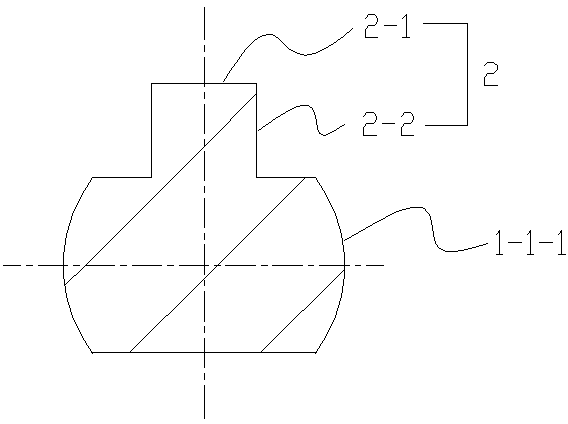
[0026] On the upper end surface of the cold-rolled steel wire, there are six equally divided bosses 2 radially pressed along the circumference of the spiral circle 1-1. The bosses 2 are longitudinally distributed at a certain angle on the spring circumference, and the bosses 2 include planar bosses. The upper end surface 2-1 and the two vertical side surfaces of the boss 2-2, the upper en...


PUM


Abstract

The invention discloses a novel spiral bushing and a reverser thereof. The novel spiral bushing comprises a spiral bushing body, wherein the spiral bushing body is formed by a plurality of spiral coils; and a plurality of bosses are formed on the spiral bushing body, and enable gaps to be formed between the adjacent spiral coils on the spiral bushing body. The novel spiral bushing and the reverser thereof can achieve good processability, can prevent the bushing from moving in the reverser in the axial direction and the radial direction, and saves cost.

Description

[0001] technical field [0002] The invention belongs to the field of commutators, in particular to a novel spiral bushing and a commutator thereof. Background technique [0003] The Chinese patent with the application number 200510137744.9 discloses a bush, which is used to be sleeved on a shaft and inserted in the shaft hole of a drive wheel. The shaft hole is non-circular, and it is characterized in that the bush The sleeve includes: a body with a small diameter portion, a first locking portion extending from the bottom of the small diameter portion, a top extending from the bottom end of the first locking portion, and a second locking portion extending from the top end of the small diameter portion, at least one connecting portion extending from the top end of the second locking portion, a clamping portion extending from the top end of the connecting portion, and a shaft hole penetrating the body for the shaft Through, wherein, the shape of the peripheral edge of the fi...

Claims


Application Information

Patent Timeline
Patent Type & Authority Applications(China)
IPC IPC(8): H01R39/04
Inventor 赵吉峰孙瑞良罗刚许刚位曾兵李国法
Owner HUARUI ELECTRICAL APPLIANCE
Learn More