Eureka AIR delivers breakthrough ideas for toughest innovation challenges, trusted by R&D personnel around the world.

Optical system analysis design method based on energy conservation law

A technology of energy conservation law and optical system, applied in the field of optical design, it can solve the problems of no optical system, quality estimation of imaging system with optical film added by optical film processing method, compatibility of optical film, etc., to achieve clear interpretation, rapid evaluation and analysis and the effect of optimizing the design

Inactive Publication Date: 2013-07-31
CHANGCHUN INST OF OPTICS FINE MECHANICS & PHYSICS CHINESE ACAD OF SCI
View PDF5 Cites 8 Cited by
  • Summary
  • Abstract
  • Description
  • Claims
  • Application Information

AI Technical Summary

Problems solved by technology

[0004] The purpose of the present invention is to solve the problem that the existing optical design software cannot reasonably estimate the quality of the imaging system added with the optical film, resulting in the incompatibility of the optical system obtained by processing the optical film with the optical film. An optical system analysis and design method based on the law of energy conservation, used for evaluation analysis and optimal design of filmed optical systems

Method used


Image

  • Optical system analysis design method based on energy conservation law
  • Optical system analysis design method based on energy conservation law
  • Optical system analysis design method based on energy conservation law

Examples


Embodiment Construction

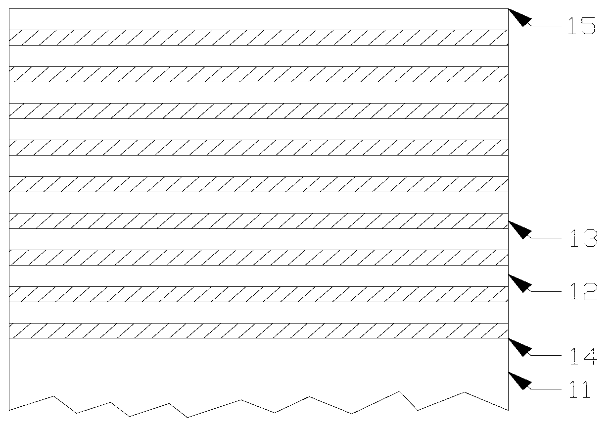
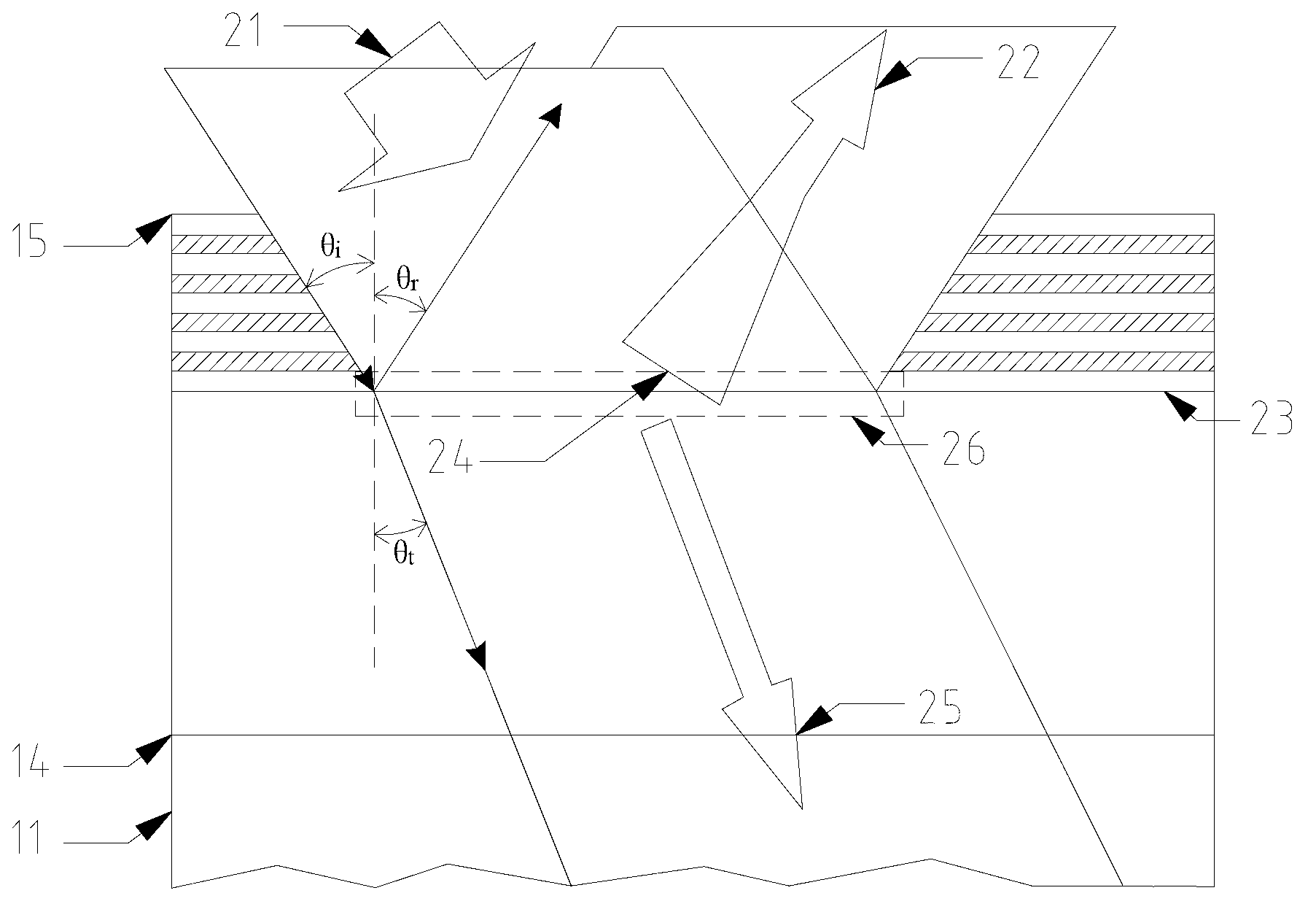
[0023] figure 1 and figure 2 It is the core principle diagram of the present invention, combined with figure 1 and figure 2 The construction principle of the equivalent working interface in the analysis and design of the optical system of the present invention is described.

[0024] figure 1 It is a schematic diagram of a coated optical element formed after adding an optical film on the optical substrate 11. The optical film is generally a multilayer film system, which is composed of a first film layer 12 and a second film layer 13 arranged alternately. The first film layer 12 and the second film layer 13 are arranged alternately. The second film layer 13 is made of two materials with different refractive indices, 14 is the bottom surface of the optical film, which is coplanar with the surface of the optical substrate 11, and 15 is the surface of the optical film.

[0025] figure 2 is the effect diagram obtained according to the equivalent working interface after the l...


PUM

PropertyMeasurementUnit
thicknessaaaaaaaaaa

Abstract

The invention provides an optical system analysis design method based on an energy conservation law and belongs to the field of optical design. The method solves the problems that a processing mode of the existing optical design software for an optical thin film cannot predict the imaging quality of the optical system additionally provided with the optical thin film reasonably, so that the designed and processed optical system is not compatible with the optical thin film. The method establishes an equivalent working interface from energy modulation by taking a strict electromagnetic field theory as a starting point, constructs the equivalent optical system additionally provided with the optical thin film according to bare optical system parameters, and evaluates and analyzes the system. The method overcomes defects in processing the optical thin film with the existing optical design software, a complicated physical optic course in the optical thin film is equivalent to a geometrical optic course, and the time and cost are saved in comparison with the existing optical software.

Description

technical field [0001] The invention relates to an optical system analysis and design method based on the law of energy conservation, which can be applied in the evaluation analysis and optimization design of the optical system, and belongs to the field of optical design. Background technique [0002] Extreme ultraviolet lithography (EUVL) uses 13.5nm extreme ultraviolet light (EUV) as the working wavelength. Almost all substances are opaque to this wavelength and have a refractive index close to 1. Therefore, the EUVL system must use a total reflection system and must be in The mirror surface is coated with Mo / Si reflectivity-enhancing optical film. The thickness of the existing Mo / Si film used in extreme ultraviolet lithography is about 300nm, which is much larger than its working wavelength. According to the strict electromagnetic field theory calculation, after the light energy enters a certain depth in the film, its energy will be completely reflected back to the In a ...

Claims


Application Information

Patent Timeline
Patent Type & Authority Applications(China)
IPC IPC(8): G02B27/00G03F7/20
Inventor 王君王丽萍金春水
Owner CHANGCHUN INST OF OPTICS FINE MECHANICS & PHYSICS CHINESE ACAD OF SCI
Why Eureka
Eureka Blog
Learn More