A high-speed mud pulse generator

A technology of mud pulse and generator, which is applied in the field of high-speed mud pulse generator and mud pressure pulse generator, and can solve the problems of low reliability, weak pulse signal and low transmission rate, etc.

Active Publication Date: 2016-01-13
DONGYING ZEBANON PETROLEUM TECH CO LTD
View PDF6 Cites 0 Cited by
  • Summary
  • Abstract
  • Description
  • Claims
  • Application Information

AI Technical Summary

Problems solved by technology

Most of these products come from foreign obsolete technologies, which have problems such as low reliability, poor high-temperature performance, low transmission rate, and weak pulse signals. There is an urgent need to replace and update products using new technologies

Method used


Image

  • A high-speed mud pulse generator

Examples


Embodiment Construction

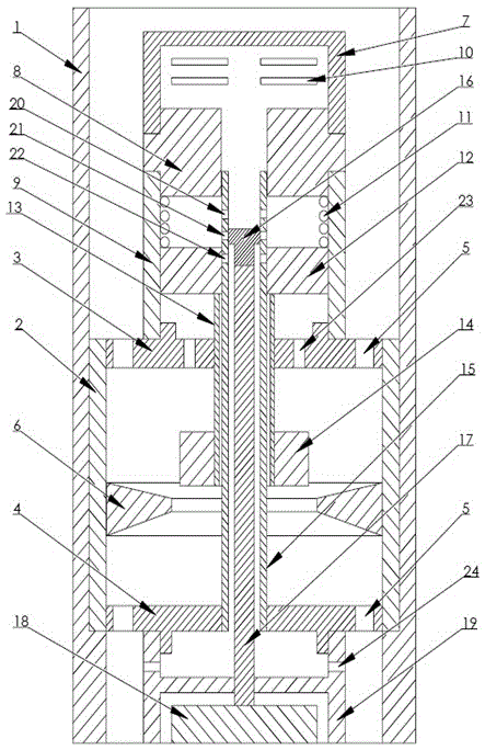
[0017] The technical scheme of a high-speed mud pulse generator is: the high-speed mud pulse generator consists of a flow tube assembly, a main valve assembly, a drive assembly, a through-shaft assembly and a hanging drill collar; the flow barrel assembly consists of a flow barrel, a throttle ring, an upper mounting plate, and a lower mounting plate; the main valve assembly consists of a mud filter, an upper joint of the piston chamber, 1 piston chamber, 1 force spring, 1 piston, 1 piston connecting rod, and 1 movable valve; the drive assembly consists of 1 driver and 1 driver chamber; the through shaft assembly consists of 1 control valve , 1 driving shaft and 1 through shaft. The flow tube assembly is installed inside the hanging drill collar, the main valve assembly is installed on the upper part of the flow tube assembly, the drive assembly is installed on the lower part of the flow tube assembly, and the through shaft assembly is located in the center of the device, conne...


PUM


Abstract

A high-speed slurry pulse generator comprises a flowing cylinder, a restrictor ring, an upper part mounting plate, a lower part mounting plate, a slurry filter, a piston bin upper part connector, a piston bin, an original force spring, a piston, a piston connecting rod, a moving valve, a control valve, a driving shaft, a though shaft, a driver, a driver bin and the like. The device uses pressure difference produced at the two ends of the restrictor ring, the piston is driven by the control valve, and the moving valve is driven to move to change overflow area of the restrictor ring to cause pressure impulse. A pressure-release hole and a spacing hole in the though shaft are adopted for piston spacing, and the high-speed slurry pulse generator has the characteristics of energy conservation, high speed and high reliability. When the driver adopts an electromagnet, sliding open-and-close control to the control valve can be performed so as to produce impulse pressure waves; and when the driver adopts a reducing motor, continuously rotating open-and-close control to the control valve can be performed, so as to produce continuous pressure wave and carry out wireless data transmission while drilling.

Description

technical field [0001] The invention belongs to the field of petroleum drilling engineering, and relates to a mud pressure pulse generator, in particular to a high-speed mud pulse generator. Background technique [0002] In oil drilling operations, with the application of measurement-while-drilling, logging-while-drilling, geo-steering, and rotary-steering technologies becoming more and more popular, it is necessary to obtain real-time information such as geological data collected by downhole measurement devices and status data of downhole devices. It is transmitted to the ground, enabling ground engineers to control the data and information from downhole in a timely manner, so as to complete drilling operations efficiently and with high quality. At present, the device that transmits these data and information from downhole to the ground is mainly a mud pulse generator. [0003] Due to the characteristics of drilling operations, it is impossible to use wired cables to conne...

Claims


Application Information

Patent Timeline
Patent Type & Authority Patents(China)
IPC IPC(8): E21B47/18
Inventor 任勇
Owner DONGYING ZEBANON PETROLEUM TECH CO LTD
Why Eureka
Try Eureka