
Millimeter wave ultra-wideband spatial power combining network

An ultra-broadband, millimeter wave technology, applied in waveguide devices, electrical components, connecting devices, etc., can solve the problem of millimeter wave frequency band taking into account broadband and high synthesis efficiency, unable to cover the frequency range of 18GHz-40GHz, rectangular waveguide main mode Limited working bandwidth and other issues, to achieve the effects of small loss, smooth frequency response, and good integration and installability

Inactive Publication Date: 2013-07-24
10TH RES INST OF CETC
View PDF5 Cites 18 Cited by
  • Summary
  • Abstract
  • Description
  • Claims
  • Application Information

AI Technical Summary

Problems solved by technology

However, the existing spatial power combiners mostly use rectangular waveguides as the main transmission line of radio frequency signals. Due to the limited operating bandwidth of the main mode of the rectangular waveguide, such as the standard rectangular waveguides WR34 and WR28, the main mode operating bandwidths are 18GHz-26GHz and 26GHz-40GHz respectively. , unable to cover the frequency range of 18GHz-40GHz
[0005] In summary, the existing power combining technology is still difficult to meet the two requirements of broadband and high combining efficiency in the millimeter wave frequency band

Method used


Image

  • Millimeter wave ultra-wideband spatial power combining network
  • Millimeter wave ultra-wideband spatial power combining network
  • Millimeter wave ultra-wideband spatial power combining network

Examples


Embodiment Construction

[0019] The present invention will be further described below in conjunction with drawings and embodiments.

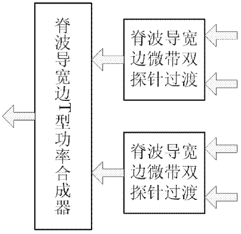
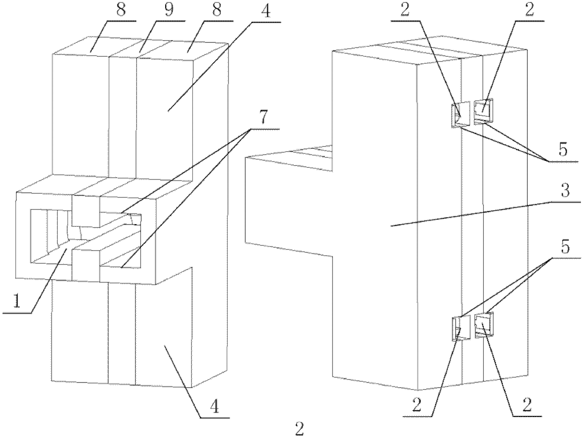
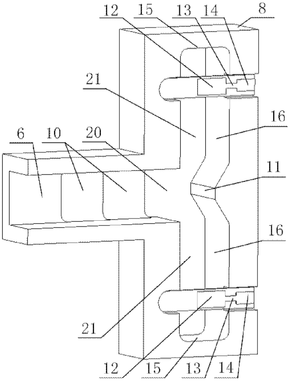
[0020] figure 1 The described power combining network based on ridge waveguide includes two parts: ridge waveguide broadside T-shaped power combiner and ridge waveguide broadside microstrip double-probe transition. The ridge waveguide wideside T-shaped power combiner adopts T-shaped connector 3 to synthesize the radio frequency signal from the upper and lower non-standard single-ridge waveguides 21 to the standard double-ridge waveguide output port 1; The double probes 12 are symmetrically inserted from the wide side 16 of the single-ridge waveguide 21 of the non-standard single-ridge waveguide 21 to both sides of the single-ridge back 19 of the waveguide, and the radio frequency signal is transferred from the microstrip double-probe 12 to the standard single-ridge waveguide 21. At the same time, two-way power synthesis is realized.

[0021] The single ridge waveguide...


PUM


Abstract

The invention provides a millimeter wave ultra-wideband spatial power combining network. Radio-frequency signals are combined to a standard double-ridge-waveguide output port (1) from four micro-strip transmission line input ports (2). Micro-strip double probes (12) are vertically inserted in from a single-ridge-waveguide broadside (16) and are distributed on two sides of waveguide single ridges (19) in a face-to-face mode. Radio-frequency signals on micro-strip transmission lines (14) are transferred into non-standard single ridge waveguides (21), and the radio-frequency signals which are transferred into an upper non-standard single ridge waveguide and a lower non-standard single ridge waveguide are combined to a non-standard double-ridge-waveguide (20) through a T-joint (3). A two-stage impedance conversion step (10) is manufactured on the inner wall of a U-shaped slot bottom of a T-shaped outer layer (8). The non-standard double-ridge-waveguide is converted into a standard double-ridge-waveguide (6), and at the same time, the radio-frequency signals are transferred to the standard double-ridge-waveguide output port (1). The waveguide single ridges (19) of the upper non-standard single ridge waveguide and the lower non-standard single ridge waveguide are respectively turned, extend to pass through the non-standard double-ridge-waveguide and ultimately enter into the standard double-ridge-waveguide to form a double-ridge (17).

Description

technical field [0001] The invention relates to an amplifier mainly used in a millimeter wave ultra-wideband power synthesis amplifier. Background technique [0002] At present, the working frequency of the relatively mature electronic countermeasure equipment developed in China is below 18GHz, while in the millimeter wave frequency band, the research on electronic countermeasure has just started, especially the demand for the core component of the millimeter wave broadband high-power solid-state power amplifier is becoming more and more urgent. The output power of broadband amplifiers in the millimeter wave band is limited. To achieve high power output, the use of power combining technology is an effective solution. Currently, the most widely used power combining technologies include circuit combining and space power combining. [0003] Broadband circuit synthesis technology usually adopts multi-stage impedance transformation Wilkinson bridge and multi-finger Lange coupler...

Claims


Application Information

Patent Timeline
IPC IPC(8): H01P5/12
Inventor 党章
Owner 10TH RES INST OF CETC
Learn More