A radio wave refraction correction method, device and system
A technology of radio wave refraction and refractive index, which is applied in the field of radio wave environment detection and radio applications, and can solve problems such as complex operation, high operating cost, and poor mobility
- Summary
- Abstract
- Description
- Claims
- Application Information
AI Technical Summary
Problems solved by technology
Method used
Image
Examples
no. 1 example
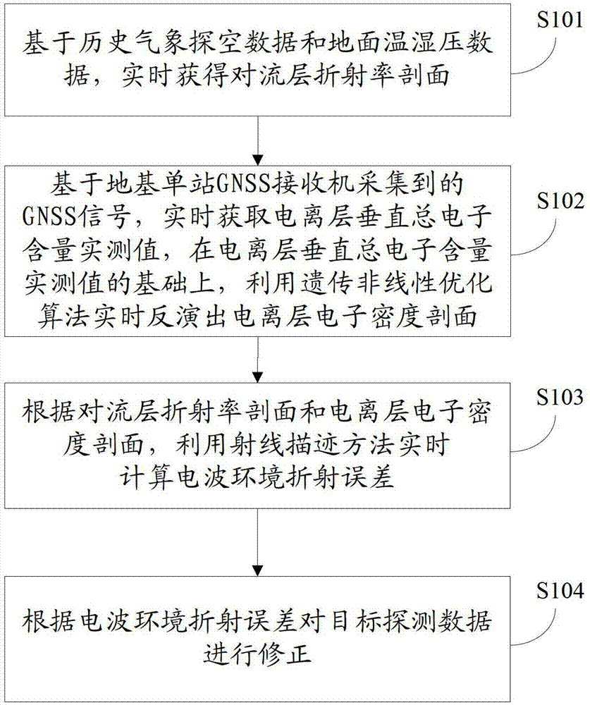
[0083] In the first embodiment of the present invention, a radio wave refraction correction method, such as figure 1 shown, including the following specific steps:
[0084] Step S101, based on historical meteorological sounding data and surface temperature and humidity pressure data, the tropospheric refractivity profile is obtained in real time.
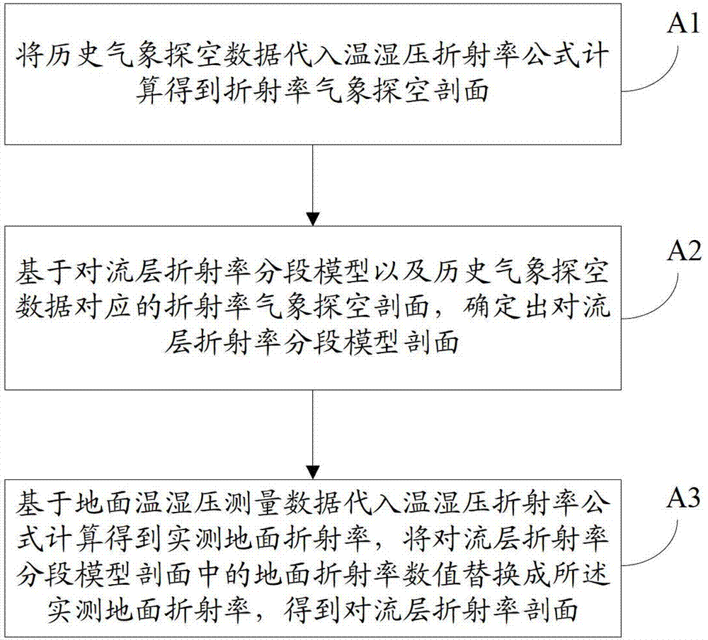
[0085] Specifically, such as figure 2 As shown, step S101 includes the following processes:
[0086] A1. Substituting the historical meteorological sounding data into the temperature and humidity pressure refractive index formula to calculate the refractivity meteorological sounding profile.
[0087] The tropospheric refractive index N′ can be expressed as a function of atmospheric state parameters (atmospheric pressure P, air temperature T, and water vapor pressure E), that is, the temperature and humidity pressure refractive index formula, as follows:
[0088] N ′ = 77....
no. 2 example
[0166] The second embodiment of the present invention is a device for implementing the radio wave refraction correction method described in the first embodiment, such as Figure 5 shown, including the following components:
[0167] The tropospheric data processing unit 100 is used to obtain the tropospheric refractivity profile in real time based on historical meteorological sounding data and ground temperature and humidity pressure data;
[0168] The ionospheric data processing unit 200 is used to obtain the measured value of the vertical total electron content of the ionosphere in real time based on the GNSS signal collected by the ground-based single-station GNSS receiver, and based on the measured value of the vertical total electron content of the ionosphere, use the genetic nonlinear The optimized algorithm inverts the ionospheric electron density profile in real time;
[0169] The refractive index error calculation unit 300 is used to calculate the radio wave environme...
no. 3 example
[0171] In the third embodiment of the present invention, a system for implementing the radio wave refraction correction method described in the first embodiment is located at the detection station. means of correction method), where,
[0172] 1. Data collection equipment, specifically comprising: a GNSS receiver for collecting GNSS signals, and a meteorological data collection unit for collecting temperature, humidity and pressure data; the meteorological data collection unit is fixedly connected to the GNSS receiver.
[0173] Further, such as Figure 6 , 7 As shown, the GNSS receiver includes: GNSS receiving antenna 501, antenna support 502 and GNSS satellite monitoring module 503 (the GNSS satellite monitoring module runs in the computer); Digital converter 506; Wherein, GNSS receiving antenna 501 is installed on the top of antenna support 502, GNSS receiving antenna 501 is connected with GNSS satellite monitoring module 503 by low-loss radio frequency line, GNSS satellite...
PUM
 Abstract
Description
Claims
Application Information
 - R&D
- Intellectual Property
- Life Sciences
- Materials
- Tech Scout
- Unparalleled Data Quality
- Higher Quality Content
- 60% Fewer Hallucinations
Browse by: Latest US Patents, China's latest patents, Technical Efficacy Thesaurus, Application Domain, Technology Topic, Popular Technical Reports.
© 2025 PatSnap. All rights reserved.Legal|Privacy policy|Modern Slavery Act Transparency Statement|Sitemap|About US| Contact US: help@patsnap.com


