
Automatic hydraulic slip

A fully automatic and hydraulic technology, which is applied to drilling equipment, earthwork drilling, drilling pipes, etc., can solve the problems of low automation, poor compatibility, and inability to adapt to pipe strings, etc., and achieves high automation, simple and safe operation, and realization of The effect of manual lubrication and automatic lubrication

Active Publication Date: 2014-12-31
BAOJI PETROLEUM MASCH CO LTD +2
View PDF4 Cites 0 Cited by
  • Summary
  • Abstract
  • Description
  • Claims
  • Application Information

AI Technical Summary

Problems solved by technology

[0004] The purpose of the present invention is to provide a fully automatic hydraulic slip, which solves the problems in the prior art that it cannot adapt to pipe strings of various diameters, poor compatibility, and low degree of automation

Method used


Image

  • Automatic hydraulic slip
  • Automatic hydraulic slip
  • Automatic hydraulic slip

Examples


Embodiment Construction

[0019] The present invention will be described in detail below in conjunction with the accompanying drawings and specific embodiments.

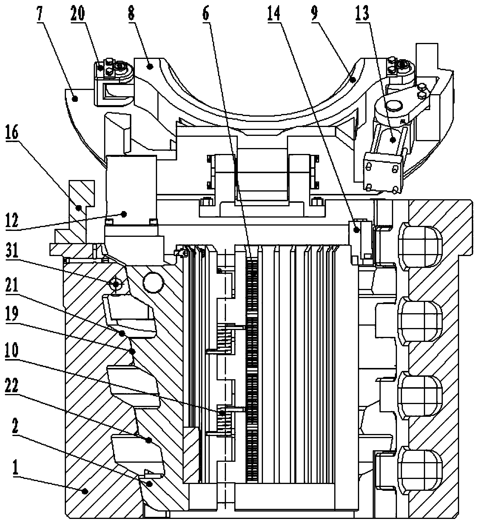
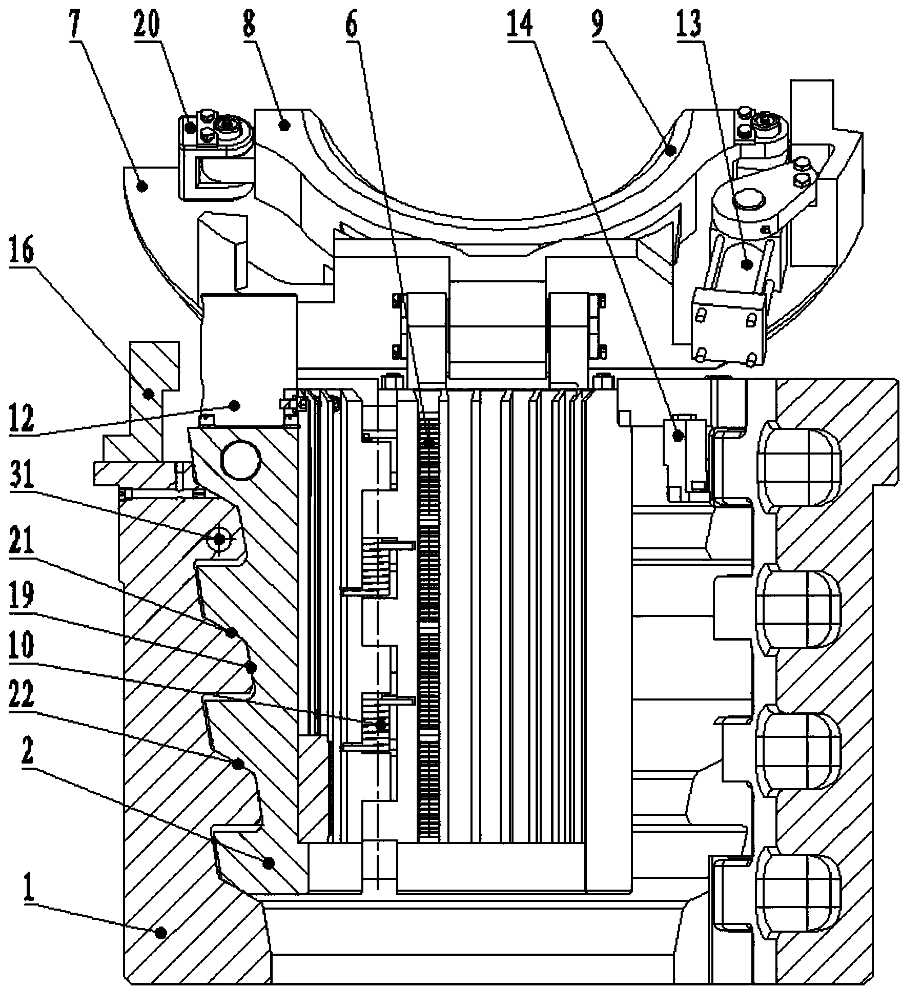
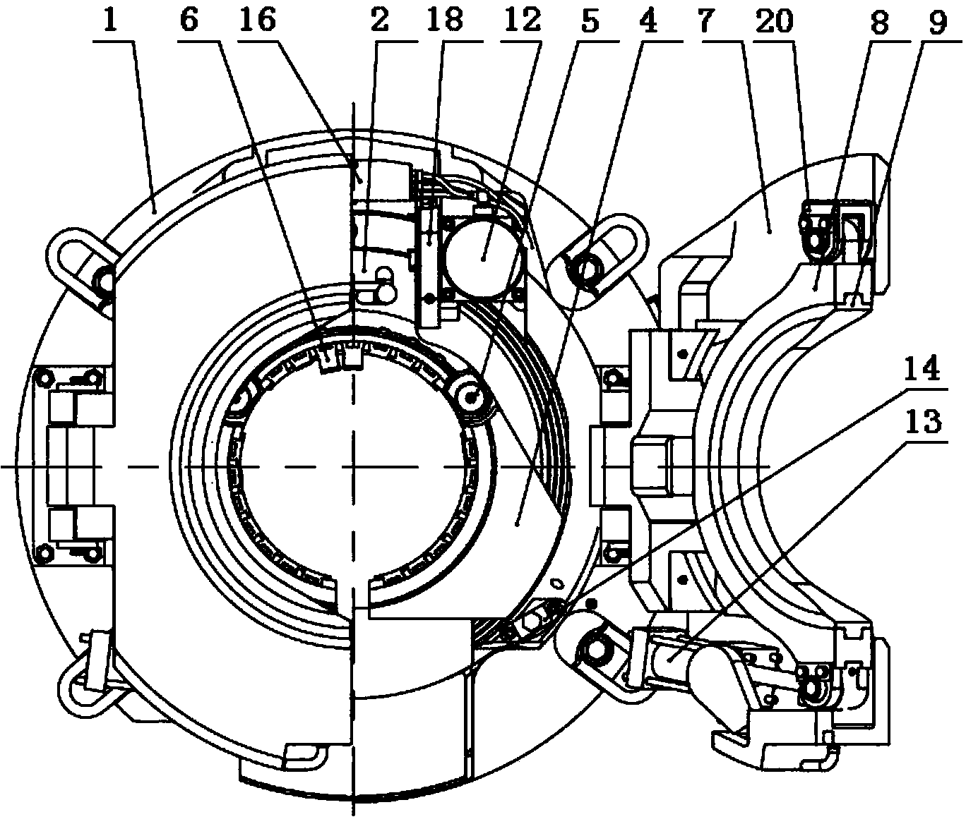
[0020] The structure of the fully automatic hydraulic slips of the present invention is that it includes a slip seat, three slip bodies, a two-petal clamping mechanism and a control mechanism, and the top cover of the clamping mechanism is equipped with a replaceable top ring clamp. And the matching top ring. The slip seat and the top cover are respectively equipped with corresponding hydraulic cylinders and integrated valve blocks, which are respectively connected to the corresponding components in the hydraulic control box 34 through their respective quick connectors; the hydraulic control box 34 is equipped with sequence valves and electromagnetic reversing valve Hydraulic components such as hydraulic components and PLC finally carry out remote operation through the control panel 35 of the driller's room.

[0021] figure 1 It is a struct...


PUM


Abstract

The invention discloses an automatic hydraulic slip, which comprises a slip base and a slip body assembly, wherein the inner surface of the clip base is longitudinally provided with a slip base slide conical surface, and the outer circular surface of the clip body assembly is also provided with a slip body slide conical surface; the upper end of the slip base is respectively hinged with a top cover, an ejector ring clip is arranged between a lug base and a clamping hydraulic cylinder on the lower surface of each top cover, and an ejector ring is embedded in the inner circular surface of each ejector ring clip; a synchronizing shaft penetrates through a transverse synchronizing shaft hole on the upper end of the slip base, the slip bases on two ends of t he synchronizing shaft hole are respectively provided with an elevation hydraulic cylinder, the opposite inner sides of the two elevation hydraulic cylinders are respectively provided with a rotating plate, each rotating plate is provided with two jacks, and two ends of the synchronizing shaft simultaneously penetrate through one jack of the rotating plate; and two telescopic shafts with identical structure are arranged in the transverse through hole on the upper end of an intermediate slip body, and each telescopic shaft is correspondently plugged into the other jack on the rotating plate. Due to the adoption of the automatic hydraulic slip, a large range for clamping a pipe column can be realized, and the automation degree is high.

Description

technical field [0001] The invention belongs to the technical field of drilling and workover equipment, and relates to a fully automatic hydraulic slip. Background technique [0002] Double elevators or one elevator and one elevator are often used in oil and gas field tripping and casing running. Double-elevator operation is inefficient and labor-intensive, and there is a potential safety hazard of serious accidents caused by single-lift ring lifting; manual slips weigh nearly 100 kg, requiring workers to move back and forth with bare hands, which also affects Increased work efficiency. [0003] The existing pneumatic and hydraulic slip structure improves work efficiency, but the clamping range is small, and the entire power slip often needs to be replaced to adapt to pipe strings of different diameters; part of the power slips rises when the pipe string is released The drilling floor is too high, which affects other operations; some hydraulic slips are loose in structure ...

Claims


Application Information

Patent Timeline
Patent Type & Authority Patents(China)
IPC IPC(8): E21B19/10
Inventor 董毅军闫永宏杨晓勇赵磊宋涛
Owner BAOJI PETROLEUM MASCH CO LTD
Learn More