Slot-in optical disk drive with lifting ejection device

a technology of lifting ejection device and which is applied in the direction of record information storage, instruments, etc., can solve the problems of uneven manufacturing quality of optical disk, drive makes the layout of internal parts and elements even more difficult, and the thickness of optical disk is too thin and too soft, so as to shorten the height of the lifting ejection device and reduce the thickness of the slot-in optical disk drive. , the effect of reducing the height of the travers

Inactive Publication Date: 2012-11-06
QUANTA STORAGE INC
View PDF3 Cites 0 Cited by
  • Summary
  • Abstract
  • Description
  • Claims
  • Application Information

AI Technical Summary

Benefits of technology

[0008]According to a first aspect of the present invention, a slot-in optical disk drive with lifting ejection device is provided. In the present invention, the thickness of the slot-in optical disk drive is reduced by shortening the height of the lifting ejection device and reducing the rising height of the traverse.
[0009]According to a second aspect of the present invention, a slot-in optical disk drive with lifting ejection device is provided. In the present invention, the force for disengaging the optical disk is increased by lifting the lifting ejection device to increase the pushing height.

Problems solved by technology

Despite the reduction in the thickness of the optical disk drive is conducive to portability, the contraction in the internal space of the optical disk drive makes the layout of internal parts and elements even more difficult.
However, the manufacturing quality of the optical disk is inconsistent.
Thinner optical disks are provided in commercial market due to cost-down consideration, or even have non-uniform thickness due to manufacturing factors, making the optical disk too thin and too soft.
Thus, the disk unloading movement may fail easily.
Therefore, the slot-in optical disk drive of prior art still has many issues to be resolved when it comes to the structure of disengaging the optical disk with the unloading lever.

Method used


Image

  • Slot-in optical disk drive with lifting ejection device
  • Slot-in optical disk drive with lifting ejection device
  • Slot-in optical disk drive with lifting ejection device

Examples


Embodiment Construction

[0020]The technologies and their effects adopted in the invention for achieving the above objects are disclosed below in a number of preferred embodiments with accompanying drawings.

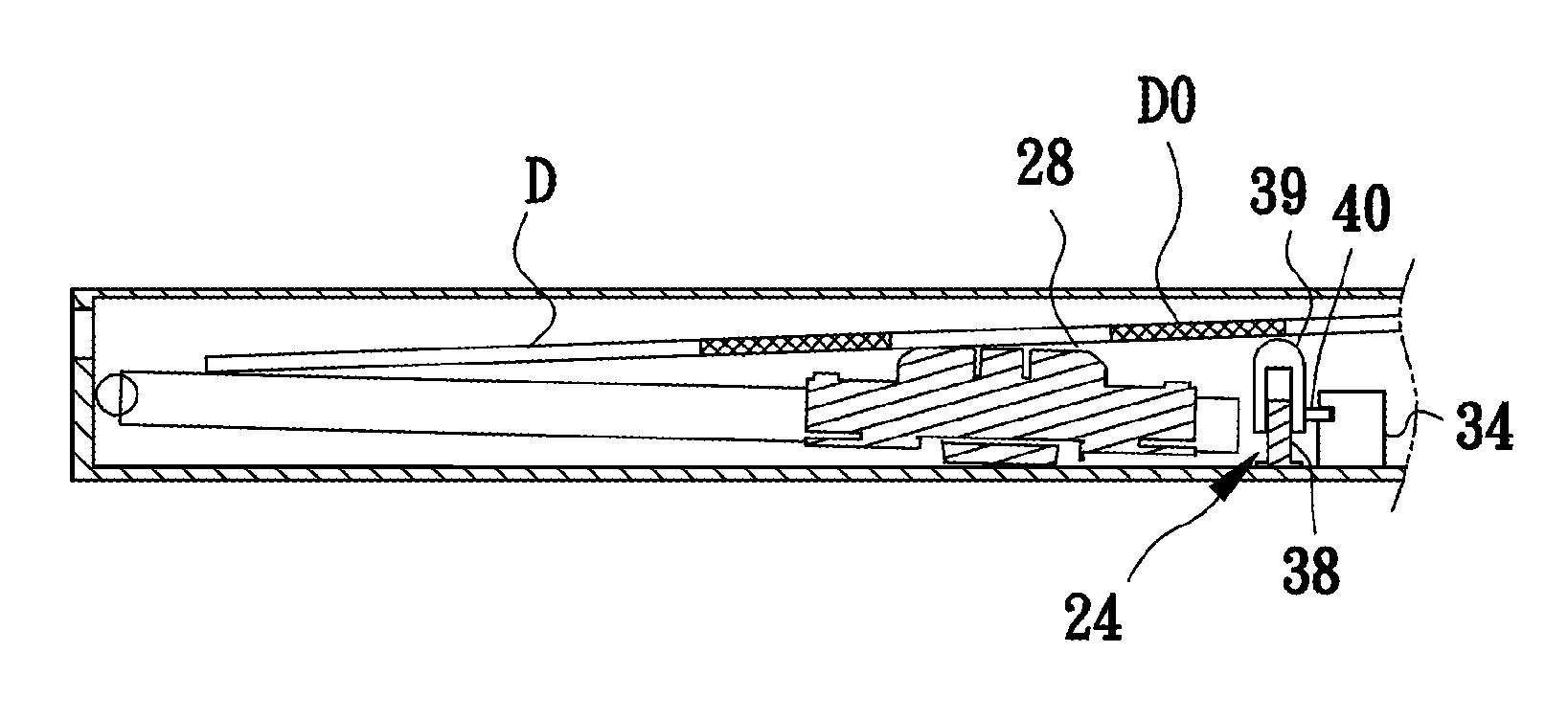
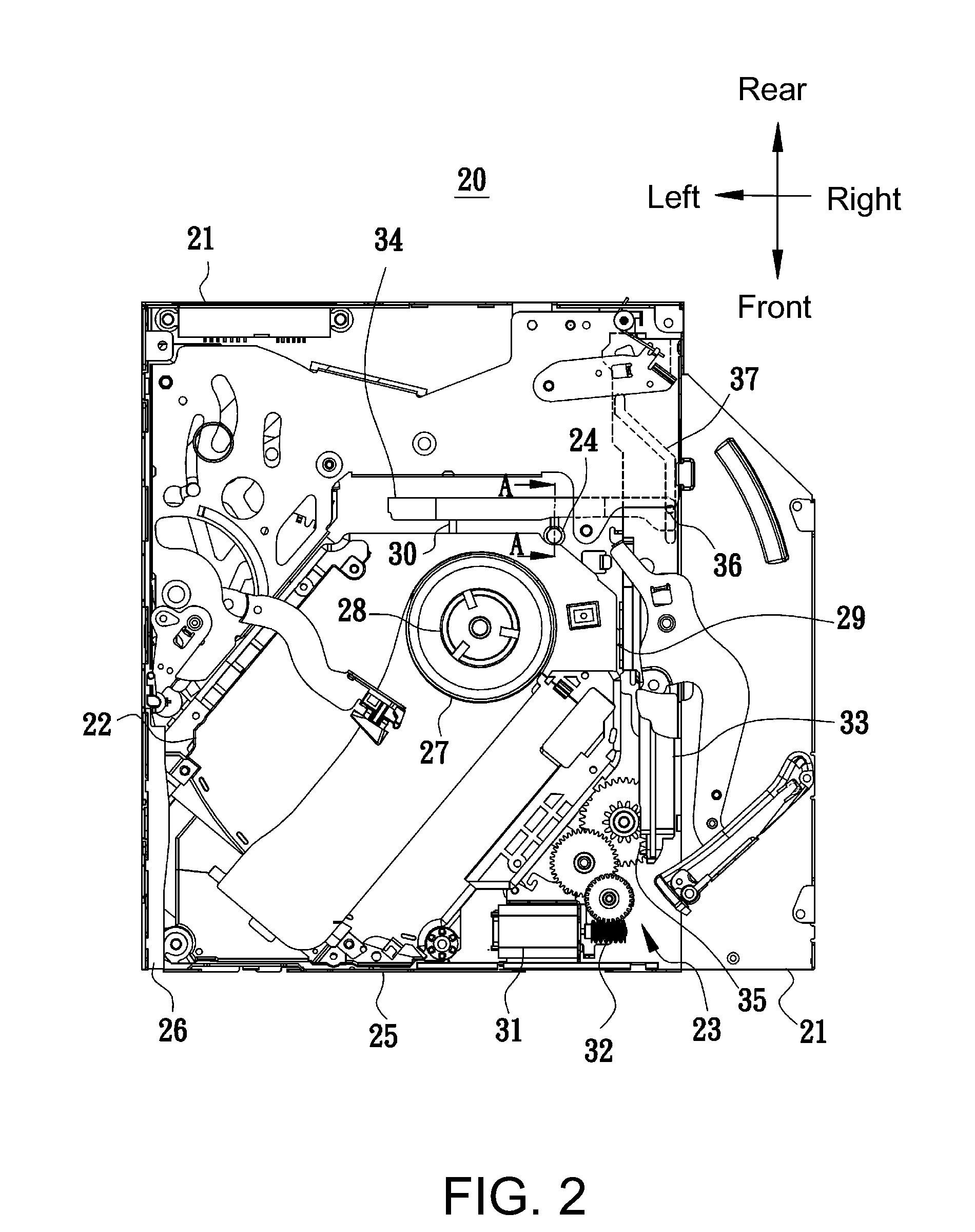
[0021]Referring to FIG. 2, a top view of a slot-in optical disk drive 20 with lifting ejection device of the invention is shown. The slot-in optical disk drive 20 includes a housing 21, a traverse 22, a transmission unit 23 and a lifting ejection device 24. The housing 21 has a hollowed inside, and the front end of the housing 21 has an entrance / exit 25 for an optical disk D (referring to FIG. 5) to pass through. The traverse 22 is disposed in the housing 21, wherein one end of the traverse 22 is pivotally connected to one side of the housing 21 towards the entrance / exit 25 and forms a pivotal end 26, which is used as a pivotal point for the traverse 22 to rotate upward and downward. The other end of the traverse 22 near the center of the slot-in optical disk drive has a spindle motor 27, and a clamping ...


PUM

PropertyMeasurementUnit
thicknessaaaaaaaaaa
poweraaaaaaaaaa
heightaaaaaaaaaa

Abstract

A slot-in optical disk drive with lifting ejection device is disclosed. A sliding device which has a first guiding slot and a second guiding slot is driven by a transmission unit. A sliding bolt protruded from a traverse is inserted into the first guiding slot, and the traverse connects with the sliding device. A lifting ejection device has a column vertically set in a housing and a sleeve which covers the column. A guiding pin protruded from the sleeve is inserted into the second guiding slot and is driven by the sliding device to disengage an optical disk.

Description

[0001]This application claims the benefit of Taiwan application Serial No. 98134445, filed Oct. 8, 2009, the subject matter of which is incorporated herein by reference.BACKGROUND OF THE INVENTION[0002]1. Field of the Invention[0003]The invention relates in general to a slot-in optical disk drive, and more particularly to a lifting ejection device of a slot-in optical disk drive which disengages an optical disk from a clamping device disposed on a spindle motor.[0004]2. Description of the Related Art[0005]Along with the rapid advance and popularity in consumer electronic products for information and communication, optical disk drives are also directed towards the trend of slimness, thinness, lightweight and compactness. Despite the reduction in the thickness of the optical disk drive is conducive to portability, the contraction in the internal space of the optical disk drive makes the layout of internal parts and elements even more difficult.[0006]As indicated in FIG. 1, a slot-in o...

Claims


Application Information

Patent Timeline
Patent Type & Authority Patents(United States)
IPC IPC(8): G11B17/04
CPCG11B17/051
Inventor HUANG, KO-HANWU, JEN-CHEN
Owner QUANTA STORAGE INC
Why Eureka
Try Eureka