
Dual-purpose device for drilling and cleaning well

A well cleaning and drilling technology, which is applied in the direction of drilling driving devices, drilling equipment, directional drilling, etc. in the wellbore, can solve the problems of troublesome follow-up work, low construction efficiency, rotten protective equipment, etc., and meet the requirements of construction conditions. The effect of high hydraulic work efficiency, easy removal and installation

Active Publication Date: 2015-05-20
CHINA MCC17 GRP
View PDF5 Cites 0 Cited by
  • Summary
  • Abstract
  • Description
  • Claims
  • Application Information

AI Technical Summary

Problems solved by technology

[0002] At present, domestic and foreign engineering construction, mining, agricultural irrigation, accident rescue, etc. all need drilling and cleaning equipment. The previous drilling machines and cleaning machines are not standardized, and there are many shortcomings, such as environmental pollution caused by high noise in the piling process; mechanical fuel consumption A large amount of cost is high and causes environmental pollution; a project often requires more construction personnel; the volume of equipment is too large, not only inconvenient for transfer and transportation, but also causes increased construction costs; low construction efficiency; The bottom of the well is uniform or the depth of the well is different, which brings troubles to the follow-up work; suspended piling is unsafe; Use on-site equipment; lack of ventilation and rescue equipment at home and abroad; labor-intensive
At present, a small, safe, reliable, low-energy and environmentally friendly dual-purpose device for drilling and cleaning has not yet appeared on the market

Method used


Image

  • Dual-purpose device for drilling and cleaning well
  • Dual-purpose device for drilling and cleaning well
  • Dual-purpose device for drilling and cleaning well

Examples


Embodiment Construction

[0017] The present invention will be further described below in conjunction with the accompanying drawings.

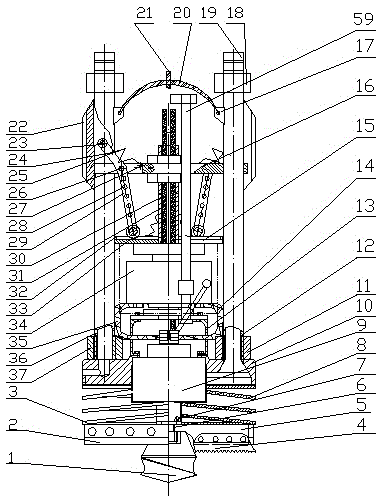
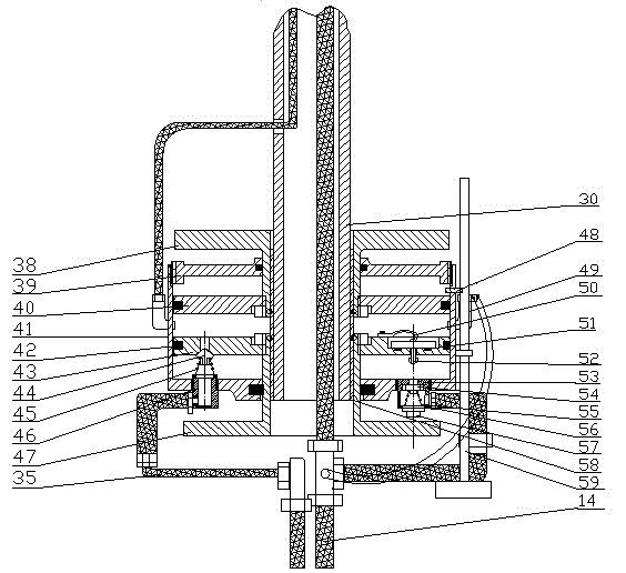
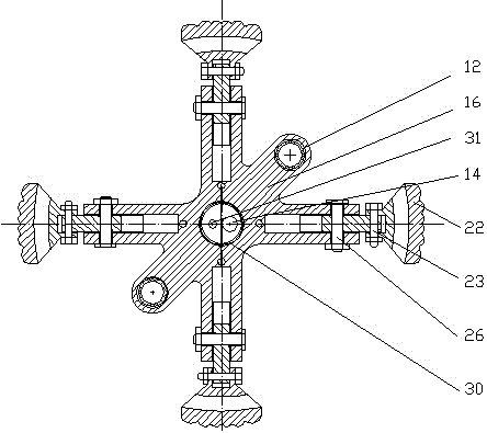
[0018] In the figure, the drilling and clearing dual-purpose device of the present invention is mainly composed of a pilot bit 1, a flat blade 2, a lifter 3, a blade tooth 4, a blade frame 5, a spline 6, a two-way sealer 7, a reinforcing steel bar 8, a hydraulic Motor 9, three-hole funnel 10, outlet pipe joint 11, outlet pipe 12, push frame 13, low-pressure hose 14, track plate 15, pressure frame 16, lug 17, connecting pipe head 18, plug-in card 19, Horizontal pull lifting rope 20, vertical pull lifting rope 21, support seat 22, pressure plate pin 23, tension spring 24, upper small hole 25, middle pin 26, lower small hole 27, adjustment hole 28, tension and pressure rod 29, hollow Pipe 30, upper high-pressure hose 31, limit block 32, roller 33, automatic control cylinder assembly 34, lower high-pressure hose 35, water supply pipe 36, water supply pipe joint 37, upper t...


PUM


Abstract

The invention discloses a dual-purpose device for drilling and cleaning a well. The device comprises a guide drill bit, shovel teeth, a lifting device, a hydraulic motor, a hydraulic automatic control oil cylinder assembly and a pressure-bearing fixing rack, wherein the hydraulic motor is mounted at the lower end of the pressure-bearing fixing rack; a lower end output shaft of the hydraulic motor is provided with a cross-shaped shovel tooth rack; the guide drill bit is mounted at the central position of the shovel tooth rack; the shovel teeth are mounted on left and right plates of the shovel tooth rack; flat shovel blades are mounted on front and rear plates of the shovel tooth rack; and the lifting device is mounted between the shovel tooth rack and the hydraulic motor. The dual-purpose device for drilling and cleaning the well disclosed by the invention has the advantages of convenience in operation, easiness of detaching and mounting, safety and reliability in utilization, small volume, light weight, convenience for transferring and improvement of working efficiency; the dual-purpose device has functions of drilling and cleaning the well, is low in noises and high in hydraulic working pressure and does not cause environmental pollution; the dual-purpose device is convenient to maintain and mount and is low in manufacturing cost; and the requirements on construction conditions are not high and the labor intensity of operators is reduced.

Description

technical field [0001] The invention relates to an engineering machinery drilling device, in particular to a dual-purpose device for drilling and cleaning with the functions of drilling and cleaning. Background technique [0002] At present, domestic and foreign engineering construction, mining, agricultural irrigation, accident rescue, etc. all need drilling and cleaning equipment. The previous drilling machines and cleaning machines are not standardized, and there are many shortcomings, such as environmental pollution caused by high noise in the piling process; mechanical fuel consumption A large amount of cost is high and causes environmental pollution; a project often requires more construction personnel; the volume of equipment is too large, not only inconvenient for transfer and transportation, but also causes increased construction costs; low construction efficiency; The bottom of the well is uniform or the depth of the well is different, which brings troubles to the ...

Claims


Application Information

Patent Timeline
Patent Type & Authority Patents(China)
IPC IPC(8): E21B7/04E21B15/00E21B4/02E21B21/00E21B12/06
Inventor 许翊像
Owner CHINA MCC17 GRP
Learn More