Pavement roller oscillation device controlled by electromagnetic clutch

A vibration starting device and electromagnetic clutch technology, applied in roads, roads, road repairs, etc., can solve the problems of not being able to stop the vibration immediately, the eccentric shaft rotates for a long time, and the loss of the power part, etc., to achieve reliable performance and simple structure , Easy installation and maintenance

Inactive Publication Date: 2013-07-24
HENAN UNIV OF SCI & TECH
View PDF6 Cites 1 Cited by
  • Summary
  • Abstract
  • Description
  • Claims
  • Application Information

AI Technical Summary

Problems solved by technology

However, using a vibrating pump or motor not only takes up a lot of space but also costs a lot, but at present, the vibrating device of the road roller is the upper method.
In addition, most of the existing vibrating devices use the high-speed rotation of the eccentric shaft to achieve vibration, which has the following defects: 1. A large torque is required to start the operation of the eccentric shaft. When the power part is suddenly loaded, the load is large, and the loss of the power part is too large; 2. Cut off the power Finally, due to inertia, the eccentric shaft will still rotate for a long time, and the vibration cannot be stopped immediately

Method used


Image

  • Pavement roller oscillation device controlled by electromagnetic clutch
  • Pavement roller oscillation device controlled by electromagnetic clutch
  • Pavement roller oscillation device controlled by electromagnetic clutch

Examples


Embodiment Construction

[0013] The embodiments of the present invention will be described in detail in conjunction with the accompanying drawings.

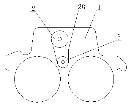
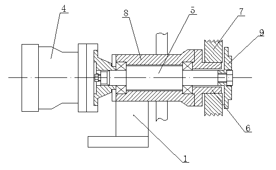
[0014] A road roller vibrating device controlled by electromagnetic clutch, including a power transmission mechanism 2 and an eccentric vibration starting mechanism 3 arranged on a road roller body 1, the power transmission mechanism 2 is composed of a driving pump 4, a transmission shaft 5, an electromagnetic clutch 6 and a transmission belt Wheel 7 is made up, transmission shaft 5 is arranged in the bearing seat 8 on the body 1 through bearing, and its one end is connected with drive pump 4 through connection plate, and the other end is connected with the clutch cover 9 of electromagnetic clutch 6 through lock nut. The transmission pulley 7 is arranged on the electromagnetic clutch 6 and is opposite to the clutch end cover 9. When the electromagnetic clutch is activated, the clutch end cover 9 can attract and rotate synchronously with the transmission p...


PUM


Abstract

The invention relates to a pavement roller oscillation device controlled by an electromagnetic clutch. A power transmission mechanism consists of a driving pump, a transmission shaft, an electromagnetic clutch and a drive pulley, wherein the drive pulley is arranged on the electromagnetic clutch and is opposite to an end cover of the electromagnetic clutch; an eccentric oscillation mechanism comprises an eccentric oscillation shaft and a driven pulley; a body of the eccentric oscillation shaft is of a cylinder shape; the shaft body is internally provided with a sliding groove which is parallel to the axial direction of the shaft body; an opening of the sliding groove is formed in the circumferential surface of one side of the shaft body; the sliding groove is internally provided with an eccentric sliding block; the bottom end of the eccentric sliding block is connected with the bottom of the sliding groove by an extension spring; and when the extension spring is in a reset state, the center of gravity of the eccentric oscillation shaft formed by the eccentric sliding block and the shaft body is positioned on the axis of the shaft body. The driving pump of a pavement roller is taken as a power source of the oscillation device, so that the effects of saving the space and reducing the cost can be realized; and the eccentricity degree of the eccentric oscillation mechanism can automatically change along with the rotating speed, so that the eccentric oscillation mechanism can be gently started, and the oscillation is rapidly stopped.

Description

technical field [0001] The invention relates to a vibrating device for a road roller, in particular to a vibrating device for a road roller controlled by an electromagnetic clutch. Background technique [0002] At present, the vibratory roller is the key equipment in the construction of high-grade highways, dams, building construction, trench foundation, pipeline backfill, etc., and the vibrating part is the key part of the vibratory roller. Most of the vibration methods of the existing rollers use vibratory pumps. or motor to achieve this. And use vibrating pump or motor not only to take up a large space but also cost high, but at present the vibrating device of road roller all is the upper way. In addition, most of the existing vibrating devices use the high-speed rotation of the eccentric shaft to achieve vibration, which has the following defects: 1. A large torque is required to start the operation of the eccentric shaft. When the power part is suddenly loaded, the...

Claims


Application Information

Patent Timeline
IPC IPC(8): E01C19/28
Inventor 郝希平吕珍龙贺健
Owner HENAN UNIV OF SCI & TECH
Why Eureka
Try Eureka