Device and method for the detection of a fungal contamination in ambient air
一种检测室、检测模块的技术,应用在支持/固定微生物的方法、特定用途的生物反应器/发酵罐、测量装置等方向,能够解决无法满足真菌污染早期检测和连续监测的需求、耗时、高成本等问题
- Summary
- Abstract
- Description
- Claims
- Application Information
AI Technical Summary
Problems solved by technology
Method used
Image


Examples
example 1
[0124] Example 1: First embodiment of the device
[0125] The preconcentrator module consists of micro preconcentrators etched on a silicon plate by DRIE process. The micro-preconcentrator consists of 20 grooves 6 cm long, with a rectangular cross-section 500 μm wide, 250 μm long, and 0.15 cm long. 3 effective volume. The groove is filled with 2,6-diphenyl ether (named TA) resin particles, the particles have an average diameter of 120 μm, a specific surface area of 35m 2 / g, porosity 2.4cm 3 / g, and an average pore size of 200 nm. The micro preconcentrator is closed by a glass plate bonded to the surface comprising the groove of the first plate.
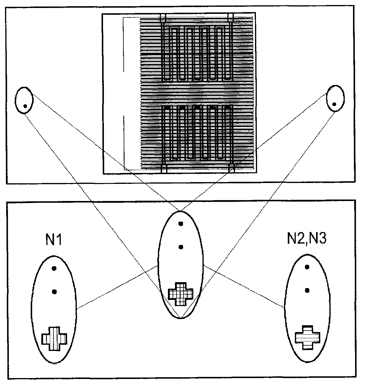
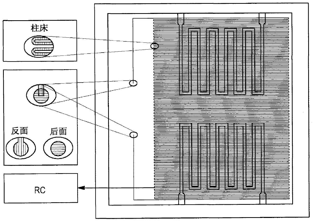
[0126] Chromatographic microcolumns are etched on silicon plates by DRIE process. The micropillars consisted of 5 m long grooves with a rectangular cross-section 150 μm wide and 200 μm long. The grooves are created in the form of parallel loops (or coils) with turns in the form of arcs to prevent the formation of dead end...
example 2
[0129] Example 2: Microcolumn calibration of the first embodiment
[0130] For the calibration, the sensor array of the device described in Example 1 was replaced by a mass spectrometer.
[0131] Table 1 lists the experimental parameters for the analytical chain.
[0132] Table 1: Characteristic parameter list of GC / MS
[0133]
[0134]
[0135] Target VOC samples were passed through the microcolumns to determine the retention time for each target VOC.
[0136] Table 2 lists the retention times for each target VOC.
[0137] Table 2
[0138]
example 3
[0139] Example 3: Experimental approach
[0140] 3.1 Experimental setup for polymer sensors
[0141] 3.1.A Data Acquisition System
[0142] The experiments were carried out with a system capable of acquiring signals from a card composed of a conductive polymer, which forms the heart of the system.
[0143] The firing cavity is placed outside the system. A filtration system including TENEX catheter Tx is located upstream of the firing chamber and ensures "clean" air make-up (leakage). Downstream of the firing chamber, a PTFE conduit enables the connection between the firing chamber and the three-way solenoid valve. All connections are made of PTFE. A three-way solenoid valve (sold by BIO-CHEM-VALVE Ltd.) makes it possible to select the reference path (air filtered by activated carbon), the sampling path (emission chamber) or the cleaning path (1-butanol / water mixture).
[0144] Pump (ESCAP company sales) can be 147 ± 1mL / min -1 Air in different climates is transport...
PUM
| Property | Measurement | Unit |
|---|---|---|
| surface area | aaaaa | aaaaa |
| size | aaaaa | aaaaa |
| specific surface area | aaaaa | aaaaa |
Abstract
Description
Claims
Application Information
 - R&D
- Intellectual Property
- Life Sciences
- Materials
- Tech Scout
- Unparalleled Data Quality
- Higher Quality Content
- 60% Fewer Hallucinations
Browse by: Latest US Patents, China's latest patents, Technical Efficacy Thesaurus, Application Domain, Technology Topic, Popular Technical Reports.
© 2025 PatSnap. All rights reserved.Legal|Privacy policy|Modern Slavery Act Transparency Statement|Sitemap|About US| Contact US: help@patsnap.com