
Conveying jig of liquid crystal display panel

A technology for liquid crystal panels and fixtures, which is applied in the direction of rigid containers, fragile goods packaging, containers, etc. It can solve problems such as the inability to take out the panel, the panel is broken, and the amplitude is large, so as to avoid fragmentation of the liquid crystal panel, prevent deformation or fragmentation, reduce The effect of small vibration amplitudes

Active Publication Date: 2013-07-24
TCL CHINA STAR OPTOELECTRONICS TECH CO LTD
View PDF5 Cites 9 Cited by
  • Summary
  • Abstract
  • Description
  • Claims
  • Application Information

AI Technical Summary

Problems solved by technology

However, due to the large size and thin thickness of large-size panels, when large-size panels need to be transported over long distances, such as experimental requirements or the situation where the front and rear process equipment are far apart, it needs to be transported across regions, floors, buildings, and factories. When the tool is in motion, the stability is poor or the flatness of the ground is poor, resulting in bumps and vibrations. If the protection is not good, it is easy to cause the panel to break
[0003] At present, there are few support points for the liquid crystal panel transfer fixture on the production line, and the amplitude of the movement is large during the transfer process, resulting in deformation or fragmentation; and the position of the panel is not fixed, and the shift will occur during the transfer process and hit the jig mechanism. Parts, resulting in corner fragments or scratches on the support surface, or interference with fixture mechanism components, resulting in the situation that the panel cannot be taken out

Method used


Image

  • Conveying jig of liquid crystal display panel
  • Conveying jig of liquid crystal display panel
  • Conveying jig of liquid crystal display panel

Examples


Embodiment Construction

[0026] It should be understood that the specific embodiments described herein are only used to explain the present invention, but not to limit the present invention.

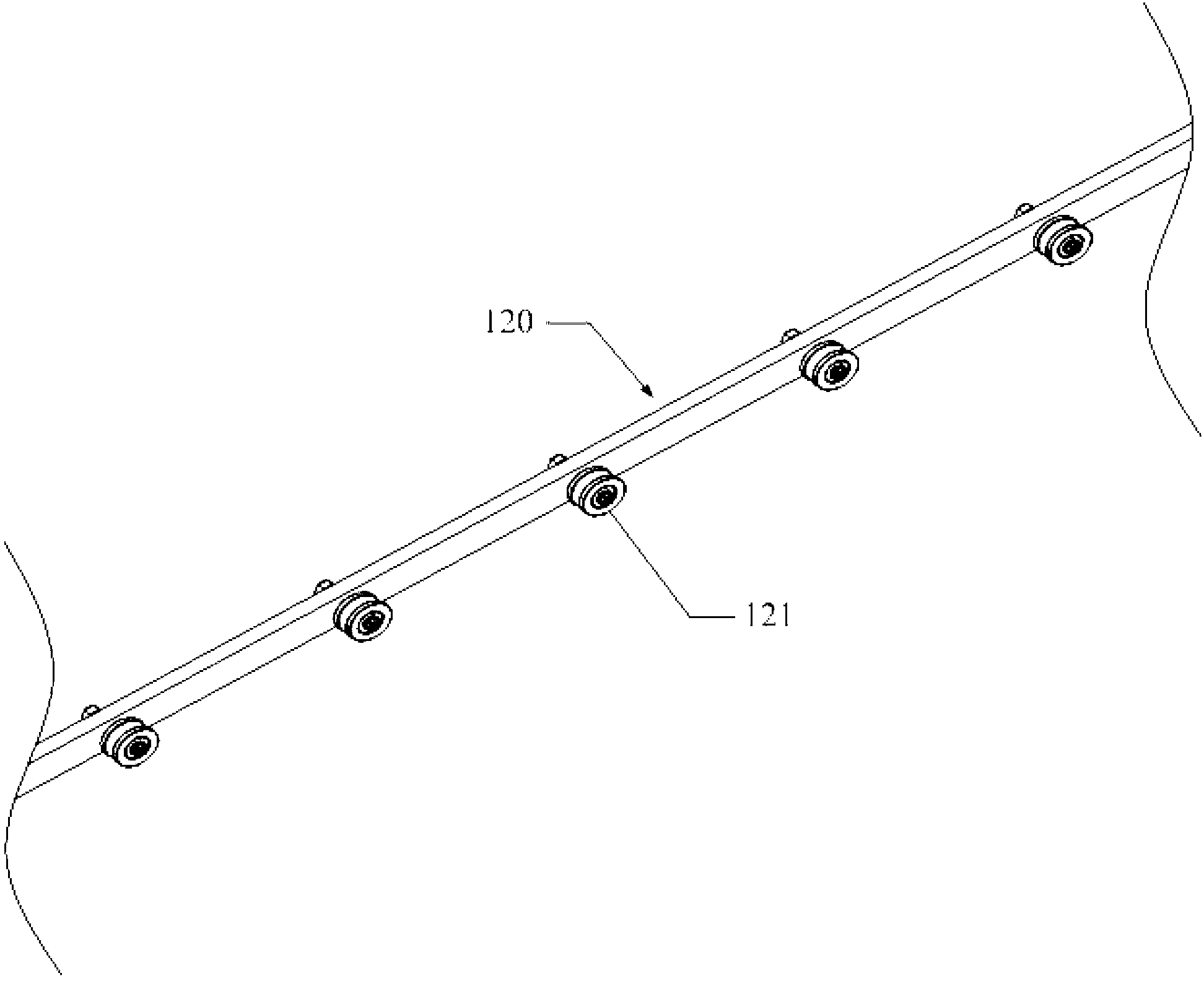
[0027] Such as figure 1 As shown, figure 1 It is a schematic structural diagram of the first embodiment of the liquid crystal panel transport jig of the present invention. The liquid crystal panel transport fixture mentioned in this embodiment includes a drawer 100 and at least one tray 200. The tray 200 is used to place a liquid crystal panel (not shown in the figure). At least one The support 110 is assembled, and the tray 200 is placed on the support 110 and slides into or out of the drawer 100 relative to the support 110. The tray 200 uses rigid hard materials to provide a flat support surface for the liquid crystal panel, increase the support point for the liquid crystal panel, reduce the vibration amplitude during the moving process, and effectively prevent the liquid crystal panel from deforming or breaking....


PUM


Abstract

The invention discloses a conveying jig of a liquid crystal display panel. The conveying jig of the liquid crystal display panel comprises a drawer cage and a tray, wherein the tray is used for accommodating the liquid crystal display panel, supporting pieces are respectively arranged on two opposite lateral walls of the drawer cage, and the tray is placed on the supporting pieces. According to the conveying jig of the liquid crystal display panel, a smooth supporting surface is provided for the liquid crystal display panel, the number of supporting points of the liquid crystal display panel is increased, vibration amplitude can be reduced when the liquid crystal display panel is conveyed, deformation or fracture of the liquid crystal display panel can be effectively avoided, force only needs to be applied to the tray when the liquid crystal display panel is placed into or taken out of the jig, and the situation of the fracture of the liquid crystal display panel caused by improper force applying when the liquid crystal display panel is placed into or taken out of the jig is effectively avoided.

Description

Technical field [0001] The present invention relates to the technical field of liquid crystal panels, and particularly relates to liquid crystal panel transport jigs. Background technique [0002] In recent years, there has been an increasing demand for large-size LCD panels over 55 inches. However, due to the large size and thin thickness of large-size panels, when large-size panels need to be transported over long distances, such as experimental requirements or the situation where the front and rear process equipment is far apart, it needs to be transported across regions, floors, buildings, and factories. When the tool is in motion, the stability is poor or the flatness of the ground is poor, resulting in bumps and vibrations. If the protection is not good, it is easy to cause the panel to break. [0003] At present, the production line used for liquid crystal panel transfer fixtures has fewer support points for the panel, and the amplitude is large during the transfer process,...

Claims


Application Information

Patent Timeline
IPC IPC(8): B65D85/38B65D19/02B65D19/38
CPCB65D85/48
Inventor 汪永强吴俊豪林昆贤齐明虎杨卫兵陈增宏舒志优蒋运芍杨国坤李晨阳子
Owner TCL CHINA STAR OPTOELECTRONICS TECH CO LTD
Learn More