Multi-band millimeter wave receiver and multi-band millimeter wave receiving method

A millimeter-wave, multi-band technology, applied in transmitter/receiver shaping network, multi-frequency modulation conversion, optical fiber transmission, etc., can solve the problem of increasing the complexity of receiver signal processing, increasing manufacturing difficulty and cost, local oscillator Problems such as high frequency can solve the design and manufacture difficulties, increase flexibility, and solve the effects of image suppression

Active Publication Date: 2013-07-17
UNIV OF ELECTRONIC SCI & TECH OF CHINA
View PDF4 Cites 15 Cited by
  • Summary
  • Abstract
  • Description
  • Claims
  • Application Information

AI Technical Summary

Problems solved by technology

This kind of zero-IF structure receiver can improve the image suppression to a certain extent, but because the frequency of the local oscillator signal is close to the frequency of the radio frequency, the local oscillator signal is easy to leak to the radio frequency transmitter, which changes the signal spectrum of the transmitter, and there is a local oscillator leak problem
Moreover, the above-mentioned receivers all use traditional baseband mixing, and the local oscillator frequency is very high, which will increase the difficulty and cost of manufacturing
In addition, in the digital signal processing part of traditional millimeter-wave receivers, digital down-conversion generally adopts digital quadrature mixing down-conversion or digital down-conversion based on polyphase filters to obtain digital baseband signals, which increases the Complexity of Receiver Signal Processing

Method used


Image

  • Multi-band millimeter wave receiver and multi-band millimeter wave receiving method
  • Multi-band millimeter wave receiver and multi-band millimeter wave receiving method
  • Multi-band millimeter wave receiver and multi-band millimeter wave receiving method

Examples


Embodiment

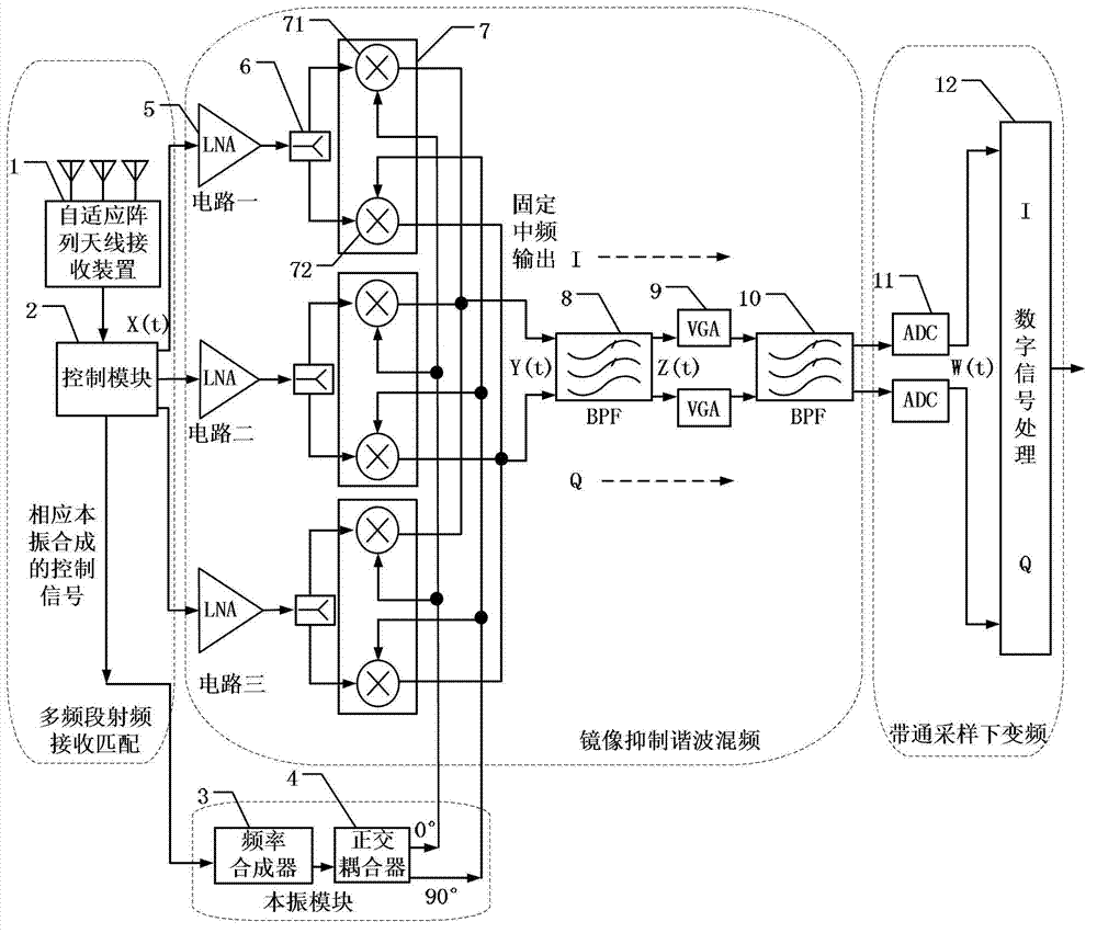
[0049] figure 1 It is a system architecture diagram of a specific embodiment of the multi-band millimeter wave receiver of the present invention. like figure 1 As shown, the multi-band millimeter-wave receiver of the present invention mainly includes a multi-band radio frequency receiving matching module, a local oscillator module, an image suppression harmonic mixing module, and a band-pass sampling down-conversion module.

[0050] The multi-band RF receiving matching module includes:

[0051] An antenna receiving device 1 whose frequency receiving range covers all frequency bands x supported by the multi-band millimeter wave receiver i , 1≤i≤X, X is the number of frequency bands supported by the multi-band millimeter wave receiver; it is used to receive the millimeter wave signal and send the millimeter wave signal to the control module 2.

[0052] In this embodiment, the antenna receiving apparatus 1 adopts an adaptive array antenna receiving apparatus.

[0053] A contr...


PUM


Abstract

The invention discloses a multi-band millimeter wave receiver and a multi-band millimeter wave receiving method. A plurality of processing circuits are used for performing orthogonal mixing frequency conversion on signals in different frequency bands to obtain a plurality of intermediate frequency signals at fixed center frequency, image signals serving as negative frequency components are removed by a plurality of band-pass filters to realize image rejection, the analogue intermediate frequency signals are simultaneously digitalized and down-converted according to a band-pass sampling theorem by an analogue-to-digital converter, and original signals of a transmitter are recovered by subsequent digital signal processing. According to the receiver and the method, image rejection performance can be improved, and system structure is simplified, and is easy to implement and integrate.

Description

technical field [0001] The invention belongs to the technical field of optical carrier wireless communication, and more particularly, relates to a multi-band millimeter wave receiver and method. Background technique [0002] ROF (Radio over Fiber, wireless access over optical) technology is an emerging research field. It combines the two technologies of optical fiber communication and wireless communication, making full use of the high bandwidth, high reliability, low loss of optical fiber transmission, and at the same time wireless The characteristics of communication mobility, point-to-multipoint access, etc., are suitable for different modulation methods and different carrier frequencies, and can be widely used in indoor coverage, mobile base station inn, broadband wireless access, vehicle mobile communication, cable TV and In terms of the composition of "ubiquitous network society", it provides users with flexible access services for various services. [0003] The main ...

Claims


Application Information

Patent Timeline
IPC IPC(8): H04L25/03H04B10/2575H03D7/16
Inventor 张崇富张巧燕邱昆李长春
Owner UNIV OF ELECTRONIC SCI & TECH OF CHINA
Why Eureka
Try Eureka