
Wood drying machine

A drying machine, wood technology, applied in the direction of drying machine, drying, local mixing dryer, etc., can solve the problems of low energy utilization rate, poor effect, limited maximum temperature, etc.

Active Publication Date: 2015-03-18
宁波天海制冷设备有限公司
View PDF8 Cites 0 Cited by
  • Summary
  • Abstract
  • Description
  • Claims
  • Application Information

AI Technical Summary

Problems solved by technology

In practical use, the wood dryer with the above structure does not have the dehumidification function. When the temperature in the drying room drops, the water vapor in the drying room will adhere to the wood again, making the wood damp again. Obviously, the effect of this drying is not good. Not good, at the same time, the dryer mentioned above is powered by a boiler, the energy utilization rate is low, and most of the boilers directly burn wood or coal to produce steam, and the products after combustion will pollute the air
In addition, due to the limited structure of the steam heat exchange system itself, the maximum temperature it can reach is limited. Generally, the temperature of the drying room can only be raised to about 50 degrees Celsius.

Method used


Image

  • Wood drying machine
  • Wood drying machine
  • Wood drying machine

Examples


Embodiment Construction

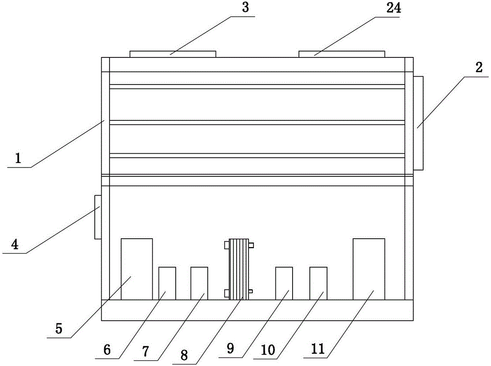
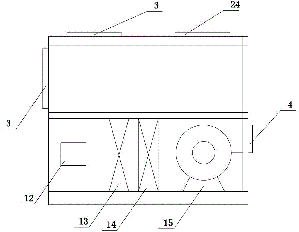
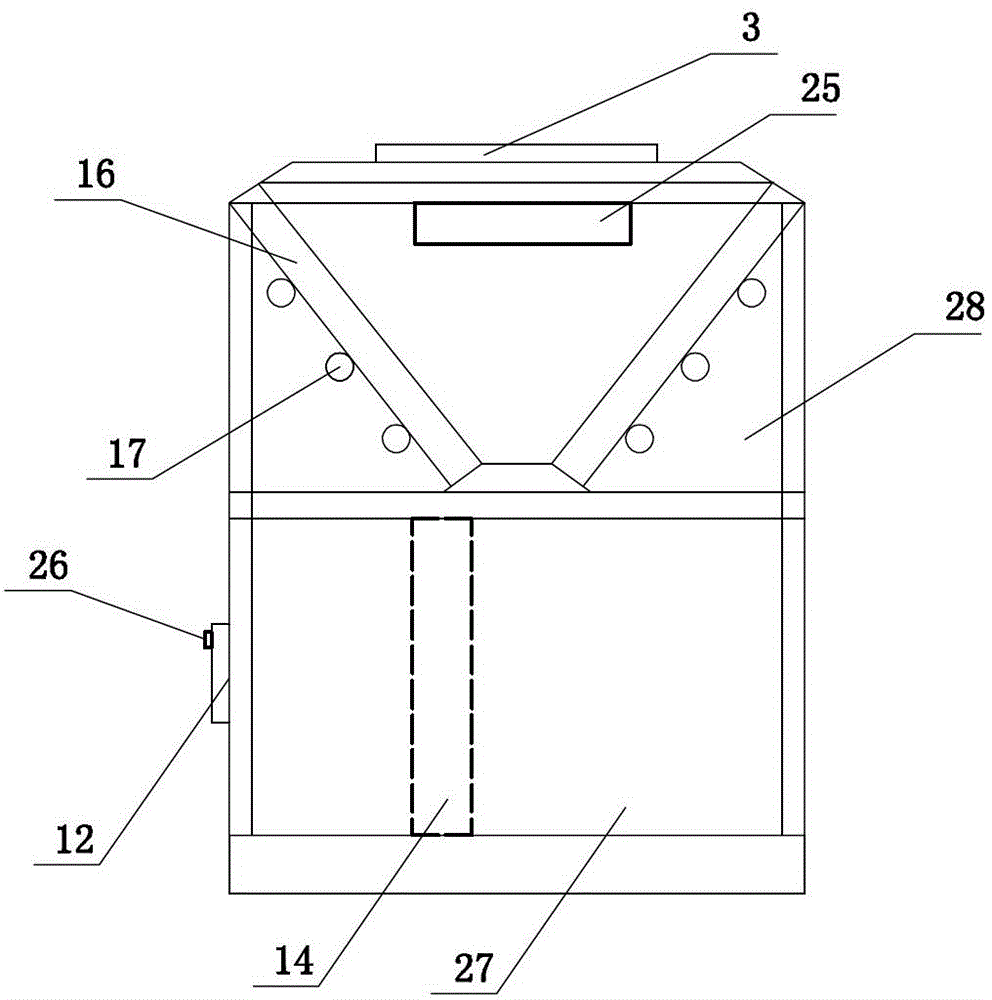
[0017] The present invention will be described in further detail below in conjunction with the accompanying drawings.

[0018] combined with figure 1 to attach Figure 4 , a wood drying machine, which includes a casing 1, a controller 2, a power supply, a low-temperature compressor 5, an intermediate heat exchanger 8, a high-temperature compressor 11, an internal evaporator 13, a condenser 14, an external evaporator 16, The first solenoid valve 18, the second solenoid valve 19, the first throttling member 20, the second throttling member 22, the temperature and humidity sensor 26, the condenser chamber 27 and the external evaporator chamber 28; the inside of the condenser chamber 27 Including the first air supply port 4, the first air return port 12 and the first air blower 15 for sending the air in the condenser chamber 27 into the drying room; the external evaporator chamber 28 includes the second air supply port 3, the second return air port The tuyere 24 and the second b...


PUM


Abstract

The invention provides a wood drying machine with high energy source utilization rate, high drying temperature and no pollution to air. The wood drying machine comprises a shell, a controller and a power source, wherein the wood drying machine further comprises a first circulating loop which is mainly formed by sequentially connecting a low-temperature compressor, a low temperature side of an intermediate heat exchanger, a first throttling part, a first electromagnetic valve and an outer evaporator, and a second circulating loop which is mainly formed by sequentially connecting a high-temperature compressor, a condenser, a second throttling part and a high temperature side of the intermediate heat exchanger; a branch which is composed of a second electromagnetic valve and an inner evaporator is connected in parallel between the first throttling part and the low-temperature compressor; a water guide device is arranged outside the inner evaporator; the shell is also internally provided with a temperature and humidity sensor, a condenser room and an outer evaporator chamber; the controller is electrically connected to each electric control part; and the power source is connected to each electrical part by wires.

Description

technical field [0001] The invention relates to a wood drying machine. Background technique [0002] In the prior art, wood dryers are widely used to dry wood for better preservation. At present, the most common wood dryers mainly generate steam by burning boilers, and then introduce the steam into the drying room through the heat exchanger, so that the drying The temperature in the room is raised to dry the wood. In practical use, the wood dryer with the above structure does not have the dehumidification function. When the temperature in the drying room drops, the water vapor in the drying room will adhere to the wood again, making the wood damp again. Obviously, the effect of this drying is not good. Not good, at the same time, the dryer is powered by a boiler, the energy utilization rate is low, and most of the boilers directly burn wood or coal to produce steam, and the combustion products will pollute the air. In addition, due to the limited structure of the steam hea...

Claims


Application Information

Patent Timeline
Patent Type & Authority Patents(China)
IPC IPC(8): F26B9/00F26B21/02
Inventor 陈玉景祝富华黄利群
Owner 宁波天海制冷设备有限公司
Learn More