LED (light emitting diode) lamp and illumination system

A technology of LED lamps and lighting systems, which is applied to lighting devices, lighting and heating equipment, and components of lighting devices, and can solve problems such as small lighting angles

Inactive Publication Date: 2013-07-17
CIVILIGHT SHENZHEN SEMICON LIGHTING
View PDF4 Cites 3 Cited by
  • Summary
  • Abstract
  • Description
  • Claims
  • Application Information

AI Technical Summary

Problems solved by technology

[0003] The purpose of the embodiment of the present invention is to provide an LED lamp, aiming to solve the problem of the small light emitting angle of the existing LED lamp

Method used


Image

  • LED (light emitting diode) lamp and illumination system
  • LED (light emitting diode) lamp and illumination system

Examples


Embodiment 1

[0015] Such as figure 1 As shown, the LED lamp provided by the embodiment of the present invention includes a bracket 11 and a plurality of LED chips fixed on the bracket 11, and the bracket 11 is formed with a first special-shaped lens 14 covering each LED chip. A second special-shaped lens 16 is molded on the lens 14, wherein the convex surface of the second special-shaped lens 16 corresponds to the concave surface of the first special-shaped lens 14, and the concave surface of the second special-shaped lens 16 corresponds to the convex surface of the first special-shaped lens 14, The LED chip is located under the convex or concave surface of the first shaped lens 14 . At this time, the convex surface of the first special-shaped lens 14 (similar to a convex lens) converges the light emitted by the LED chip to enter the second special-shaped lens 16, and the concave surface of the first special-shaped lens 14 (similar to a concave lens) emits light from the LED chip. After t...

Embodiment 2

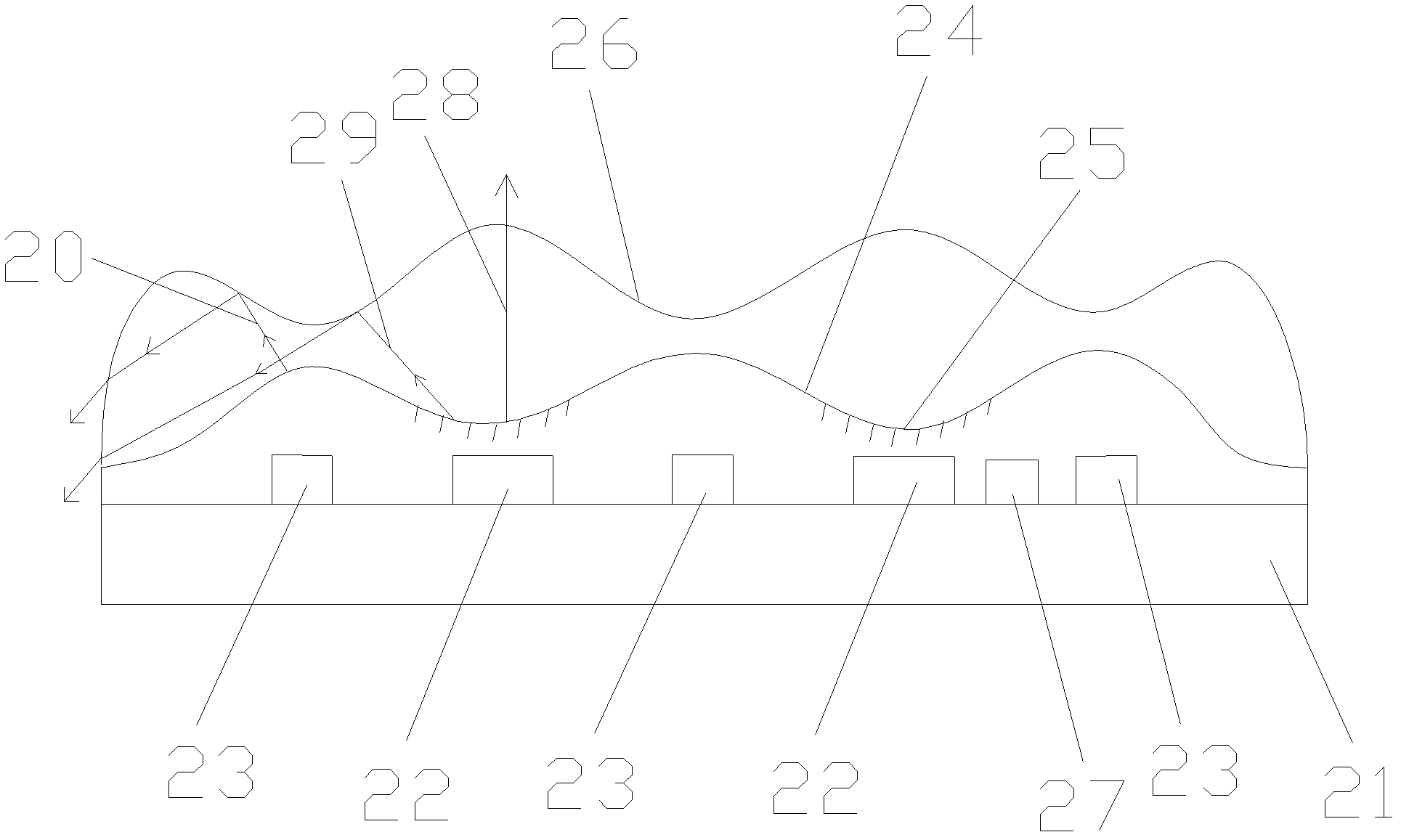
[0023] The difference from Embodiment 1 is that three red light chips 23, two blue light chips 22 and one thermistor 27 are fixedly connected to the bracket 21, and the red light chips 23 are arranged around the blue light chip 22, wherein the red light chip 23 , blue light chip 22 and thermistor 27 are connected with drive circuit by electrode line, as figure 2 shown. First, the first special-shaped lens 24 is formed on the top of the chip by one-time molding. The first special-shaped lens 24 has a plurality of concave and convex surfaces that are connected together alternately. Concave surfaces are formed, and a yellow or yellow-green phosphor layer 25 is uniformly coated on each concave surface to generate white light. Then, the second special-shaped lens 26 is formed by one-shot molding above the first special-shaped lens 24. The second special-shaped lens 26 also has a plurality of concave and convex surfaces that are connected together alternately. The convex surface ...


PUM

PropertyMeasurementUnit
Excitation wavelengthaaaaaaaaaa

Abstract

The invention is applicable to the field of semiconductor illumination and provides an LED (light emitting diode) lamp and an illumination system. The LED lamp comprises a support frame and a plurality of LED chips fixedly arranged on the support frame, wherein first special-shaped lenses covered on the LED chips are formed on the support frame, and second special-shaped lenses are formed on the first special-shaped lenses, convex surfaces of the second special-shaped lenses correspond to the concave surfaces of the first special-shaped lenses, the concave surfaces of the second special-shaped lenses correspond to the convex surfaces of the first special-shaped lenses, and the LED chips are positioned under the convex surfaces or the concave surfaces of the first special-shaped lenses. At the moment, the light sent by the LED chips is gathered by the convex surfaces of the first special-shaped lenses so that the light can enter the second special-shaped lenses, the light sent by the LED chips is scattered by the concave surfaces of the first special-shaped lenses so that the light can enter the second special-shaped lenses, so the light sent by each LED chip can be mixed in the second special-shaped lenses to form mixed light, the mixed light is emitted out after being reflected and refracted by the first special-shaped lenses and the second special-shaped lenses for many times, the luminous angle is greater than 180 degrees, and the luminous effect of a three-dimensional light source is reached.

Description

technical field [0001] The invention belongs to the field of semiconductor lighting, in particular to an LED lamp and a lighting system. Background technique [0002] Semiconductor LED lighting has the characteristics of green environmental protection, long life, high efficiency and energy saving, resistance to harsh environments, simple structure, small size, light weight, fast response, low working voltage and good safety, so it is known as the successor to incandescent lamps, fluorescent lamps and The fourth-generation lighting electric light source after energy-saving lamps, or green light source in the 21st century. However, the light-emitting angle of the existing LED lamps is relatively small, which fails to meet the requirements of large-angle light-emitting applications. Contents of the invention [0003] The purpose of the embodiments of the present invention is to provide an LED lamp, aiming to solve the problem of the existing LED lamp with a small light emitt...

Claims


Application Information

Patent Timeline
IPC IPC(8): F21S2/00F21V5/04F21V23/02F21Y101/02F21K9/20F21Y113/10F21Y115/10
Inventor 赵西刚
Owner CIVILIGHT SHENZHEN SEMICON LIGHTING
Why Eureka
Try Eureka